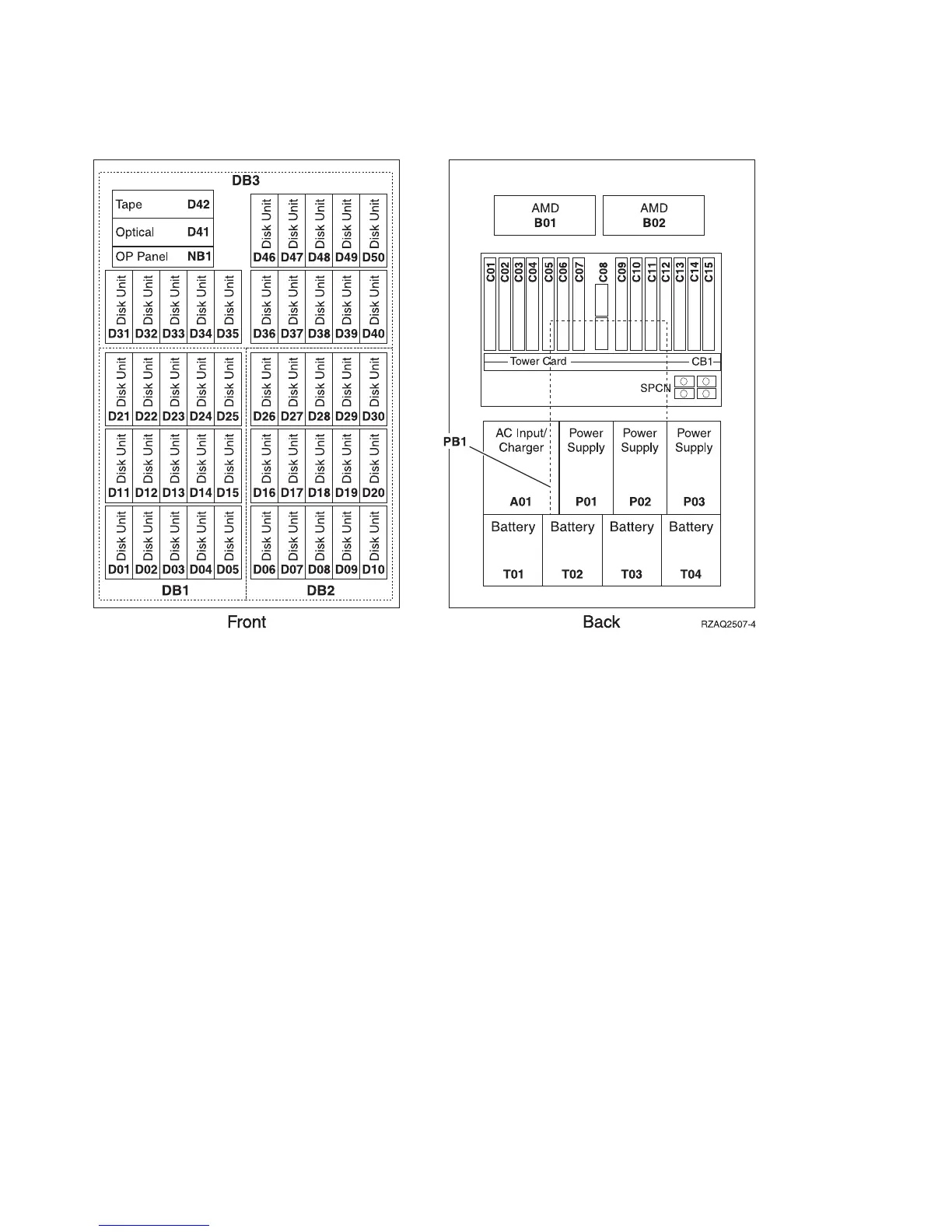
Locations — FC 5074 I/O Tower
Notes:
1. The FC 5074 I/O Tower contains two system PCI busses.
2. In the FC 5074 I/O Tower FRU Locations and Failing Components table below,
the first of the two busses in the tower is designated as ″xxxx″ and the second
bus in the tower is designated as ″yyyy″.
3. In FC 5074 I/O Tower the two bus numbers assigned to the busses are not
required to be in any order.
4. Card position C01 is required to be an I/O processor.
5. Card postitions C05 and C11 are required to be either I/O processors or
Integrated xSeries Servers (IXS).
6. J11 is an RPO connection, J14 is a Uninterruptable Power Supply connector, J15
is an SPCN 1 connector, and J16 is an SPCN 2 connector.
7. Multi-adapter Bridge domains are labeled PCI Bridge Set inside the tower.
8. The following table provides information necessary to identify the IOP to
which IOAs are assigned. The left column indicates the domain in which IOA
assignment is allowed. The right column is used to determine the IOP to which
an IOA is assigned. The first position in the list must be an IOP. The remaining
positions may be IOPs or IOAs. IOAs are assigned to the first IOP located to
their left in the list. Although IOAs can be manually reassigned using SST/DST,
the IOA assignments return to the default order after each IPL.
Figure 44. Locations for FC 5074 I/O Tower
Locations and Addresses
736
iSeries Model 830, 840, SB2, and SB3 Problem Analysis, Repair and Parts V5R1
 Loading...


