Workstation
a I/O Bus
b Adapter
cd Port
e 0
f Device
g 0
h Session
Disk, Tape, or Optical with I/O adapter
address (Type B)
a I/O Adapter
b I/O Bus
cd Controller
ef Device
gh FF
Note: If the unit (device) address appears as FFFF FFFF, the address cannot be
determined.
13. OS/400 communication-diagnostic panels that are displayed by the commands
VFYCMN, WRKPRB, and ANZPRB use the following address format:
x1 x2 x3x4
Table 75. Decimal Address Values
Value Description
x1 = System bus The one, two, or three digit decimal representation of the
hexadecimal Bus value of the Bus-Bus-Bus-Bus/Card-Card/Board-
Board format Address at the top of Figure 63 on page 939.
x2 = System board The one or two digit decimal representation of the hexadecimal
Board value of the Bus-Bus-Bus-Bus/Card-Card/Board-Board
format Address at the top of Figure 63 on page 939.
x3 = System card The one or two digit decimal representation of the hexadecimal
Card value of the Bus-Bus-Bus-Bus/Card-Card/Board-Board
format Address at the top of Figure 63 on page 939.
x4 = Adapter location The one or two digit decimal representation of the hexadecimal b
Adapter value of the Communications unit address value in step
12 on page 939.
Return to the information that sent you to this procedure.
This ends the procedure.
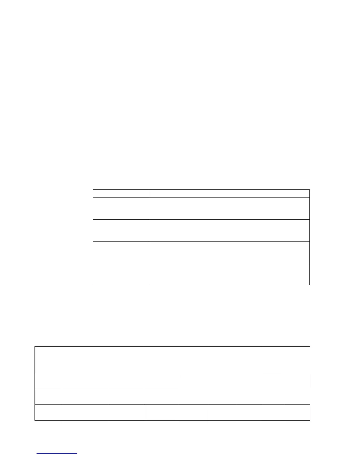
Hardware SRC Formats
Table 76. SRC format examples (other formats exist; if necessary contact your next level of support)
SRC
Word
Number
Panel Function,
Digitsxtoy
(from left to
right)
IOP SRC
Format 13
IOP SRC
Format 17
Device
SRC
Format 27
LIC SRC
Format 60
LIC SRC
Format
61
LIC
SRC
Format
62
LIC SRC
Format
63
1 11, 1-8 TTTT RRRR TTTT RRRR tttt rrrr A6xx
RRRR
B6xx
RRRR
ww00
RRRR
A600
RRRR
2 12, 1-8 MIGV EP13 MIGV EP17 MIGV
EP27
MIGV
EP60
MIGV
EP61
MIGV
EP62
MIGV
EP63
3 12, 9-16 BBBB Ccbb BBBB Ccbb BBBB Ccbb PPPP
0000
cccc cccc cccc
cccc
AAAA
BBBB
SRC Address Formats
940
iSeries Model 830, 840, SB2, and SB3 Problem Analysis, Repair and Parts V5R1