f. Remove the screws that hold the DASD shelf to the frame.
g. Remove the DASD shelf from the frame.
5. Remove the retaining screw that is holding the DASD board assembly to the
frame.
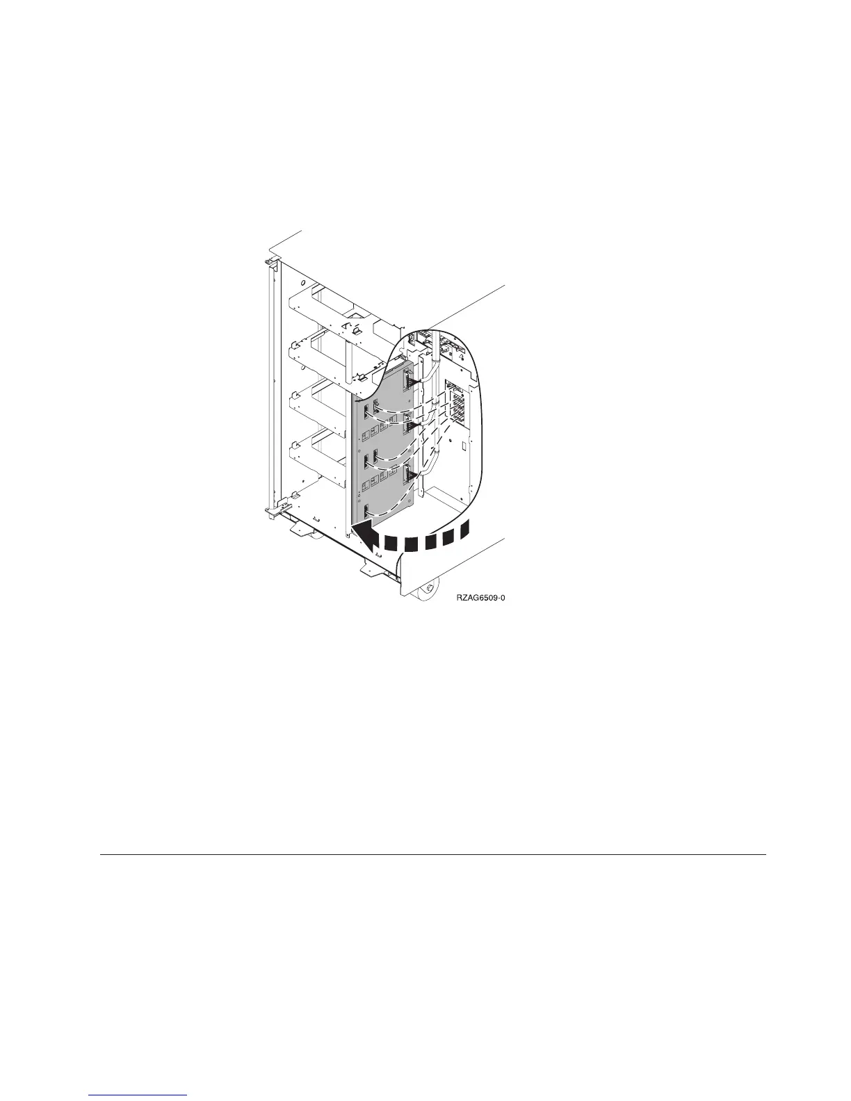
6. Pull the DASD board assembly out until it slides off the guide pins, then rotate
the DASD board assembly 90° to remove the cables that are located on the
backside of it.
7. Remove the cables from the rear of the DASD board assembly and note their
locations.
Note: Both ends of the ribbon cables are marked “LH” or “RH” indicating that
one end of the cable is plugged in to either the left-hand (DB1) or
right-hand (DB2) DASD board assembly. The other end of the cable is
plugged in to either the left-most (LH) or right-most (RH) DASD
controller card (The cables will crisscross in the center of the tower).
8. Remove the DASD board assembly.
9. Install the DASD board assembly by reversing the removal procedure. After
exchanging an item, go to “Verifying the Repair” on page 920.
This ends the procedure.
Models 830/SB2 – Device Board (DB3)
1. Power off the system. (See “Powering On and Powering Off the System and
Logical Partitions” on page 922.)
2. Disconnect the power cord from the system unit.
3. Open the rear cover. (See “Models 830/SB2 with FC 9074 – Covers” on
page 663.)
Remove and Replace Procedures
Chapter 4. Removal and Installation Procedures 665