v SPCN optical cables C between the preceding frame in the string and the
failing frame.
(A) SPCN
Optical ┌───── (C) SPCN
Adapter ────┐ │ Optical Cables
││
│ │ ┌─── (B) SPCN
┌─────────┐ │ │ │ Optical
│ System │ │ │ │ Adapter
│ Unit │ │
│ J15 │ ┌─┐ ┌─┐
└────┬────┘ │ ├────────────┤ │
│ │ ├────────────┤ │
┌────┴────┐ ┌───────┴─┤ ┌───────┴─┤ ┌─────────┐
│ J15 │ │ J16│ │ J15│ │ │
│Frame J16├─┤J15 Frame│ │Frame J16├─┤J15 Frame│
│1 ││ 2│ │3 ││ 4│
└─────────┘ └─────────┘ └─────────┘ └─────────┘
│
│
└───Failing Frame
This ends the procedure.
66. Does the SPCN frame-to-frame cable coming from the system unit connect to
J15 on the secondary frame (where the power on light is off or the frame
control panel displays a power reference code of 1xxx xxxx)?
Yes No
↓ Correct the connection by connecting the SPCN frame-to-frame cable
coming from the system unit to J15 of the secondary frame.
This ends the procedure.
67. Perform the following:
a. Power off the system.
b. Disconnect the SPCN frame-to-frame cable from J15 on the AC module or
SPCN card of the first frame or unit that cannot become powered on.
c. Connect the negative lead of a multimeter to the system frame ground.
d. Connect the positive lead of the multimeter to pin 2 of the SPCN cable.
Note: Use an insulated probe or jumper when performing the voltage
readings.
e. Note the voltage reading on pin 2.
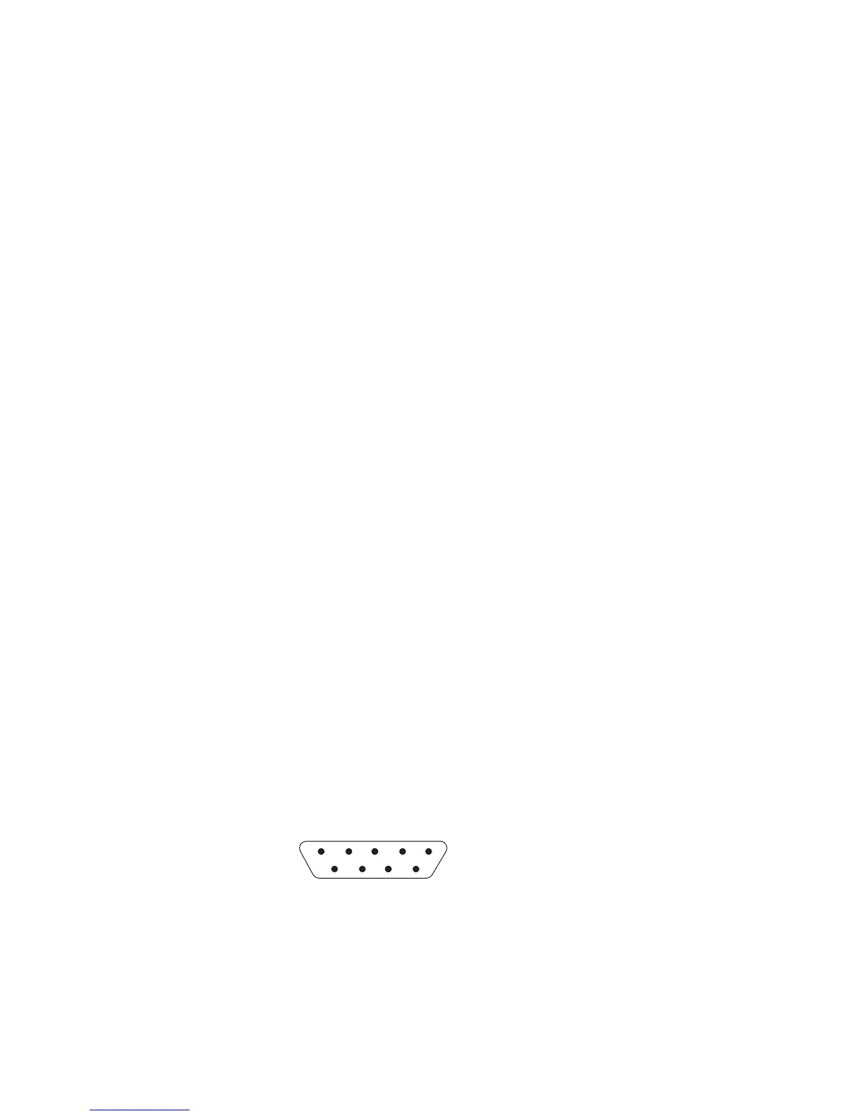
f. Move the positive lead of the multimeter to pin 3 of the SPCN cable.
g. Note the voltage reading on pin 3.
12345
6789
RV2A180-1
Is the voltage on both pin 2 and pin 3 from 1.5 V DC to 5.5 V DC?
No Yes
↓ Exchange the following FRUs, one at a time. See the removal and
installation procedures in this book or in the Migrated Expansion Tower
Problem Analysis, Repair and Parts, depending on the secondary frame
that you are working on.
Power Problems
Chapter 1. Starting Problem Analysis 55
 Loading...


