HARDWARE DESCRIPTION OF THE 8051,8052 AND 80C51
F8
FO
E8
EO
lx
Do
C8
m
S8
BO
AS
AO
98
90
88
80
8Bytes
B
ACC
Psw
(T2CON)
,
,
1
I
(RCAP2L) (RCAP2H)
I
(-m)
(TH2)
1.
I 1
[ [
,,
Ps
IE
m
I
1
1 I i 1
S&N
I
SBUF
PI
I I
I I I
I I
,
I
1 I
,
1
T&N TMOD TLO TL1 THO THI
I
Po
SP DPL
DPH
I
PCON
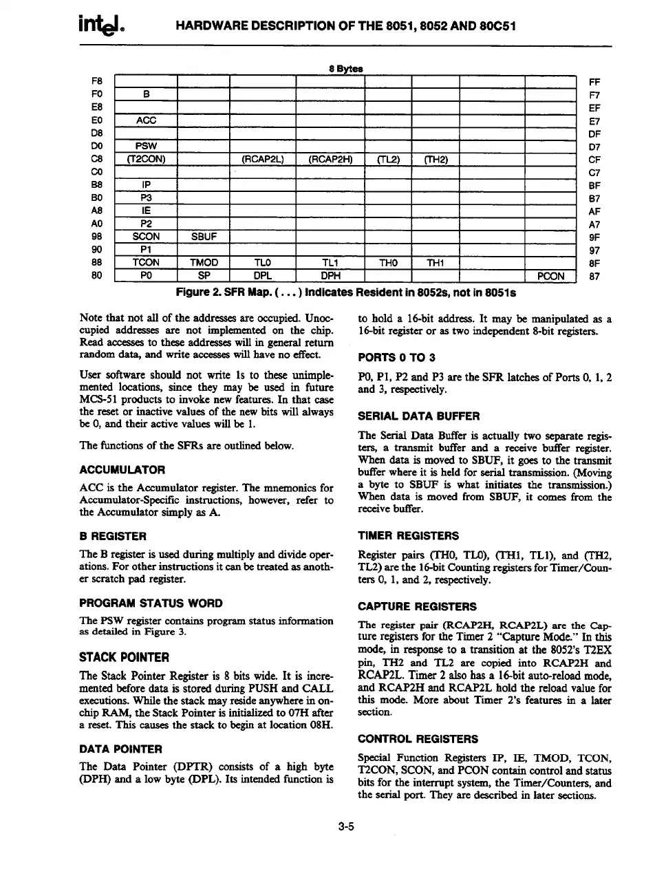
Figure 2. SFRMap. (... ) Indicates Resident in 8052s, not in 8051s
Note that not all of the addressesare occupied.Unoc-
cupied addreaaeaare not implementedon the chip.
Read accemesto theaeaddresseawillin generalreturn
randomda@ and write accesseswillhaveno effect.
User software should not
write 1s to these unimple-
mented locations, since they may be used in future
MCS-51productato invokenewfeatures.In that case
the reset or inactivevaluesof the newbits will always
be O,and their activevalueswillbe 1.
The fi.mctionsof the SFRSare outlinedbelow.
ACCUMULATOR
ACC is the Accumulatorregister.The mnemonicsfor
Accmnulator-Speciticinstructions, however, refer to
the Accumulatorsimplyas A.
B REGISTER
The
B registeris usedduringmultiplyand divideoper-
ations.For otherinstructionsit canbetreatedasanoth-
er scratch pad register.
PROGRAM STATUS WORD
The PSWregister containsprogramstatus information
as
detailedin Figure 3.
STACKPOINTER
The StackPointer Register is 8 bitswide.It is incre-
mentedbeforedata is stored duringPUSHand CALL
executions.Whilethe stack mayresideanywherein on-
chipRAM,the StackPointeris initializedto 07H after
a reset.This causesthe stack to beginat location08H.
DATA POiNTER
The Data Pointer (IXTR) consists of a high byte
(DPH) and a lowbyte (DPL). Its intendedftmctionis
FF
F7
EF
E7
DF
D7
CF
c?
BF
B7
AF
A7
9F
97
8F
87
to hold a 16-bitaddress. It may be manimdatedas a
id-bit registeror as twoind~-dent 8-bit-registers.
PORTS O TO 3
PO,Pl, P2 andP3 are
the SFR latches of Ports O,1,2
and 3, respectively.
SERiAL DATA BUFFER
The Serial Data ButTeris actually two separate regis-
ters, a t
ransmit butTerand a receive butTerregister.
When&ta is movedto SBUF,it goesto the transmit
bufferwhereit is heldfor aerialtransmission.(Moving
a byte to SBUF is what initiatea the transmission.)
When data is movedfrom SBUF, it comes from the
receivebuffer.
TIMER REGiSTERS
Register pairs (THO,TLO),(TH1, TL1), and (TI-D,
TL2)are the id-bitCountingregistersforTimer/Coun-
ters O,1,and 2, reqectively.
CAPTURE REGiSTERS
The register pair (RCAP2H RCAP2L) are the Cap-
ture registetxfor the Timer 2 “Capture Mcde.” In this
mode, in responseto a transition at the8052’sT2EX
pin, TH2 and TL2 are copied into RCAP2H and
RCAP2L. Timer 2alsohas a 16-bitauto-reloadmode,
and RCAP2Hand RCAP2Lhold the reloadvaluefor
this mode. More about Timer 2’s festures in a later
section.
CONTROL REGiSTERS
Special Function Registers 1P, IE, TMOD, TCON,
T2CON,SCON,and PC(3Ncontaincontrolandstatus
bits for the interrupt system,the Timer/Count~ and
the serial port. Theyare describedin later sections.
3-5