8XC52/54/58 HARDWAREDESCRIPTION
Table 4. Timer 2 Operating Modes
RCLK + TCLK
cPlm
TR2
MODE
o
0 1
16-BitAuto-Reload
I
o
I
1
Ill
16-BitCapture
I
I
1
I
x
Ill
BaudRateGenerator
I
I
x I x
Iol
oft-l
I
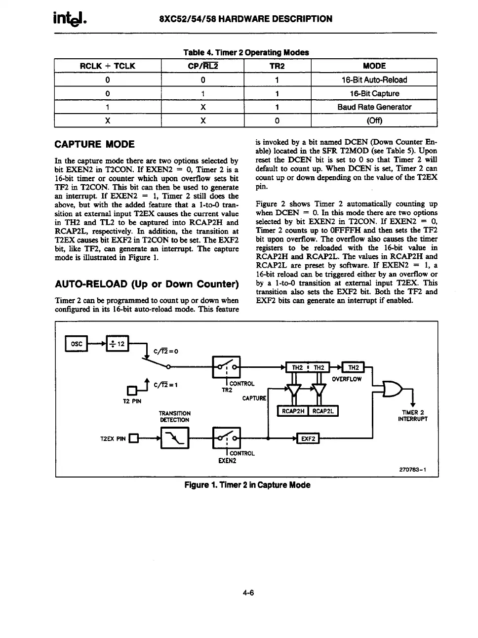
CAPTURE MODE
In
the capture mode there are two options selected by
bit EXEN2 in T2CON. If EXEN2 = O,Timer 2 is a
16-bit timer or counter which upon overfiow sets bit
TF2 in T2CON. This bit can then be used to generate
an interrupt. If EXEN2 = 1, Timer 2 still does the
above, but with the added feature that a 1-to-Otran-
sition at external input T2EX eauaes the current value
in TH2 and ‘fZ2 to be captured into RCAP2H and
RCAP2L, respectively. In additio~ the transition at
T2EX esuaes bit EXF2 in T2CON to be set. The EXF2
bit, like TF2, ean generate an interrupt. The capture
mode is illustrated in Figure 1.
AUTO-RELOAD (Up or Down Counter)
Timer 2 can be programmedto count up or down when
contlgursd in its 16-bit auto-reload mode. This feature
is invoked by a bit named DCEN (Down Counter En-
able) located in the SFR T2MOD (see Table 5). Upon
reset the DCEN bit is set to Oso that Timer 2 wilf
default to count up. When DCEN is set, Timer 2 can
count up or down depending on the valueof the T2EX
pin.
Figure 2 shows Timer 2 automatically counting up
when DCEN = O.In this mode there are two options
selected by bit EXEN2 in T2CON. If EXEN2 = O,
Timer 2 counts up to OFFFFH and then sets the TF2
bit upon overflow. The overtlow also causes the timer
registers to be reloaded with the 16-bit value in
RCAP2H and RCAP2L. The values in RCAP2H and
RCAP2L are preset by software. If EXEN2 = 1, a
16-bitreload can be triggeredeither by an overfiow or
by a l-to-O transition at external input T2EX. This
transition also sets the EXF2 bit. Eoth the TF2 and
EXF2 bita ean generatean intemupt if enabled.
OJ
c/E =1
I CONTROL
TR2
-.m-..--
T2 PIN
LAt’l UKt.
I II
TRANSITION
OUECTION
piaiim I +
TIMER2
INTERRUPT
T2EX PIN
+X1 ~
I
I CONTROL
EXEN2
2707S3-1
Figure1.Timer2inCaptureMode
4-6