intd.
8XC51FXHARDWAREDESCRIPTION
8.7 Response Time
——
The INTO and INT1 levels are inverted and latched
into the InterruptFlags IEOand IE1 at S5P2 of every
machine cycle. Similarly, the Timer 2 flag EXF2 and
the serial Port tlags RI and TI are set at S5P2. The
values arenot actually polled by the circuitry until the
next machine cycle.
The TimerOand Timer 1flags, TFOand TFl, are set at
S5P2 of the cycle in which the timers overflow. The
values arethen polled by the circuitryin the next cycle.
However, the Timer 2 flag TF2 is set at S2P2 and is
polled in the same cycle in which the timer overflows.
If a requestis activeand conditions areright for it to be
acknowledged, a hardware subroutine call to the re-
quested serviceroutinewill be the next
instructionto be
executed. The call itself takes two cycles. Thus, a mini-
mum
of threecomplete machine cycleselapseabetween
activation of an external interrupt requestand the be-
ginning Ofexecution of the service routine’s @t in.
struction. Figure 25 shows
interrupt response timing.
A longer response time would result if the request is
blocked by one of the 3 previouslylisted conditions. If
an interrupt of equal or higher priority level is already
in Proaress,the additional wait time obviouslvdmends
or writeto IE or IP, the additional
wait time cannot be
more than 5 cycles (a maximum of one ormore cycle to
complete the instruction in progress, plus 4 cycles to
complete the next instruction if the instruction is MUL
or DIV).
Thus,ina single-interruptsystem, the response time is
always more than 3 cycles and less than 9 cycles.
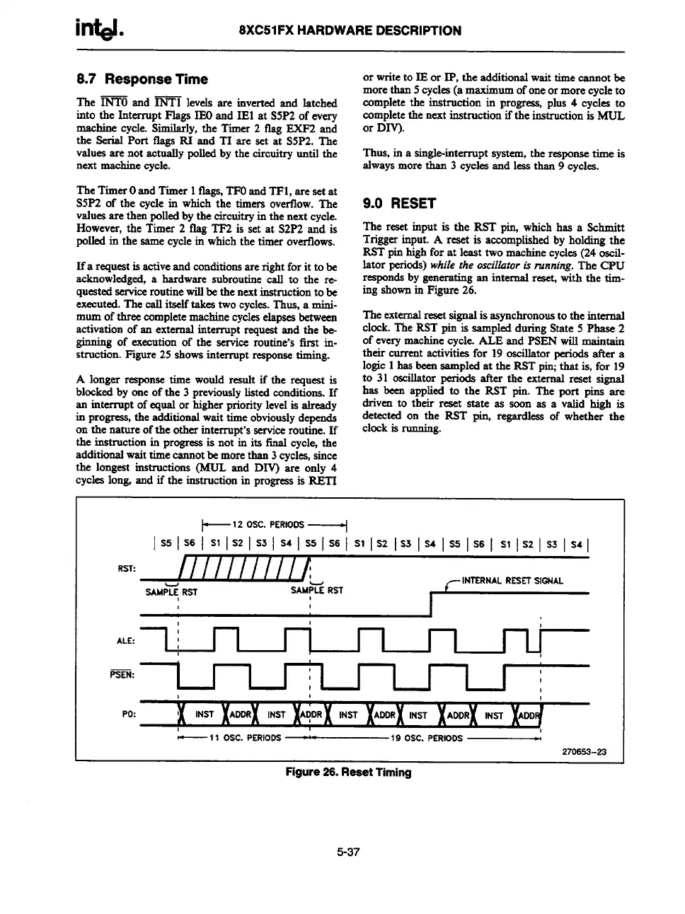
9.0 RESET
The reset input is the RST pirLwhich has a Schmitt
Triggerinput. A reset is accom
plishcd by holding the
RST pin high for at least two machine cycles (24 oscil-
lator periods)while the Oscilbtor is running. The CPU
r~nds by generating an internal r= with the tim-
ing shown in Figure 26.
The externalresetsignal is asynchronousto the internal
clock. The RST pin is sampled during State 5 Phase 2
of everymachine cycle. ALE and PSEN will maintain
their current activities for 19 oscillator periods after a
logic 1 has been sampled at the RST pirLthat is, for 19
to 31 oscillator periods after the external reset signal
has been applied to the RST pin. The port pine are
driven to their reaet state as soon as a valid high is
detected on the RST pin, regardkas of whether the
on-the-natureof the other interrupt’sservice;outine. If
clock is
running.
the instruction in progressis not in its final cycle+the
additional wait time cannotbe more than 3 cycles, since
the longest instructions (MUL and DIV) are only 4
cycles long, and if the instruction in progressis RETI
~12 OSC. PERIODS-----+
I S5 I S6 I S1 I S2 ] S3 I S4 I S5 I S6 I S1 I S2 I S3 I S4 I S5 I S6 I S1 I S2 I S3 I S4 [
RST:
//////////!
~lNTERNAL RESETSIGNAL
SAMP~ RST
SAMP~E RST
,
1
I
,
,
1
ALE:
,
PSEN:
,
I
I
I
I
I
I
I
I I I
I
,
I
Po:
~
INST
INST
ADDR
f
I
—11
OSC. PERIoDS —
19 OSC. PERIODS _
270653-23
Figure 26. Reset Timing
5-37