intel.
HARDWARE DESCRIPTIONOF THE 8051,8052 AND 80C51
clock signalis gated off to the CPU. In PowerDown
(PD = 1),the oscillatoris frozen.The Idleand Power
Down modes are activated by setting bits in Special
FunctionRegisterPCON. The addressof this regiete.r
is 87H.Figure26details ita contents.
In the HMOSdeviceathe PCONregisteronlycontains
SMOD.The other four bits are implementedonly in
the CHMOSdevices.User softwareshouldneverwrite
1s to unimplementedbita, since they may be used in
t%tureMCS-51products.
IDLE MODE
An
instructionthat sets PCON.Ocausesthat to be the
last instruction executed before going into the Idle
mode. In the Idle mode, the internal clock signal is
gatedoff to the CPU, but not to the Interrupt, Timer,
and SerialPort functions.The CPU statueis preserved
in its entirety: the Stack Pointer, Program Counter,
ProgramStatueWord, Accumulator,and all otherreg-
isters maintain their data during Idle. The port pins
hold the logicalstatea they had at the time Idle was
activated.ALEand PSEN hold at logichighlevels.
Thereare twowaysto t-ate the Idle.Activationof
any enabledinterropt willcausePCON.Oto be ckared
byhardware termma
“ ting the Idle mode.Theinterrupt
willbe aervic@ and followingRETI the next instruc-
tion to be executedwill be the one followingthe in-
structionthat put the deviceinto Idle.
riOh
2rAL2
‘L...
b--
Figure 27. Idle and Power Down Hardware
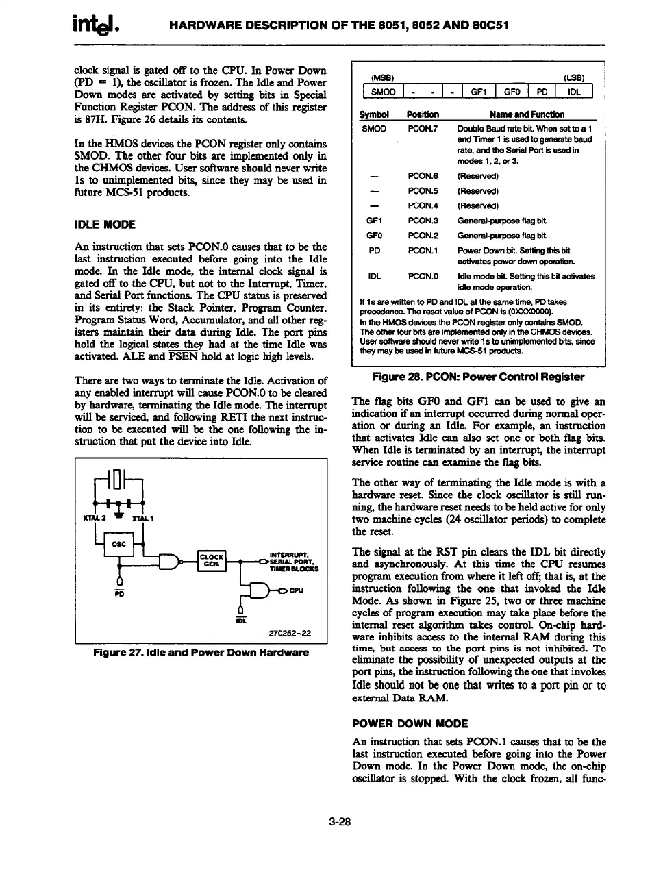
(MSB)
(Lss)
SMOO
I - I - I -
GF1 GFO PD IOL
symbol PoSnIOrt
Natrteattd Furtotic+t
SMOD PCON.7
OoubleSaud rats bit.When aattoa 1
and Timer 1 isusedtogenerrda baud
rate, andfhs SsrW .%rl isusedin
modes 1,2, 0r3.
PCON.6
(Reserved)
FCON.5
(Reserved)
—
PCON.4
(Reaswsd)
GF1 PCON.3
General-purposeflagbit
GFO PCX2N.2
Gemaraf-pu~ flqlrit.
PD
FCX2N.I
Powsr DownM. Satfingthisbit
activates powsrdewmoperation.
IDL
PCON.O
Idle mode bit.Setfingthk btiactivataa
idlemode opsratiort
If 1s arewrfrrento PD and IDL at the aametime, PDfskes
precedence.l%areeetvaluaof PCONia(OXXXOCOO).
Intfw HMOSd-
* ~N @2taroII~contains SMOD.
Ttwofherfcurtit eareimpkmer!tsd onfyintlw CHMOSdsvioea.
User mftwsre sfwuldrwverwite Istourimplememtsd bita,ainm
tfwymaybeuasdin future MCS-51 pmduote.
Figure 28.
PCON:PowerControlRegister
The tlag bite GPOend GFI can be used to give an
indiesti;n ifen interrupt occurredduringnorm~ oper-
ation or during an Idle. For
example,an instruction
that activates Idle can also set one or both flag bita.
WhenIdle is terrmna
“ ted by an interrupt, the interrupt
serviceroutinecan
examinethe fig bita.
The other wayof termma
“ ting the Idle modeis with a
hardware reset. Sincethe clock oscillatoris still run-
ning the hardwareresetneedsto beheldactivefor only
two machinecycles(24oscillatorperiods)to complete
the reset.
The signalat the RST pin clears the IDL bit directly
and asynchronously.At this time the CPU resumes
programexecutionfrom whereit leftoff;that is, at the
instruction followingthe one that invokedthe Idle
Mode.As shownin Figure 25, two or three machine
cyclesof programexecutionmay take pleeebeforethe
internal reset algorithm takes control. On-chiphard-
ware inhibitaaccess
to the internal RAM during this
time, but aeccasto the port pins is not inhibited.To
eliminatethe possibilityof unexpectedoutputs at the
port pine,the instructionfollowingthe onethat invokes
Idle shouldnot be one that writes to a port pin or to
externalData RAM.
POWER DOWN MODE
An
instructionthat seta PCON.1cauaeathat to be the
last instruction executedbefore goinginto the Power
Down mode. In the Power Down mode, the on-chip
oscillator is stopped. With the clock frozen,all func-
3-28