i~e
MCS@-51 ARCHITECTURAL OVERVIEW
When the CPU is executing from intemrd Program
Memory, ~ is not activated, and program address-
es are not emitted. However, ALE continues to be acti-
vated twice per machine cycle and so is available as a
clock output signal. Note, however, that one ALE is
skipprd during the execution of the MOVX instmction.
Interrupt Structure
The
8051 core provides 5 interrupt sources 2 external
interrupts, 2 timer interrupts, and the serial pat inter-
rupt. What follows is an overview of the interrupt
structure for the t3051.Other MCS-51 devices have ad-
ditional interrupt sources and vectors as shown in Ta-
ble 1. Refer to the appropriate chapters on other devic-
es for further information on their interrupts.
INTERRUPT ENABLES
Each of the interrupt sources can be individually en-
abled or disabled by setting or clearing
a bit in the SFR
(MSB)
(LSB)
EAl —
I—IESIETI IEXIIETOIEXO
Enablebk = 1 enablesb interqf.
Ensblebk =odieabksit
symbol Pmiti9n
Function
EA
IE.7
d&bles all intempts. If EA = O,no
interruptW be acknowledged.If EA
= 1, each intenupt source is
itiiuslfy enabled or disebled by
settingw clearingiteeneblebit.
—
IE.6
reserved”
—
IE.5
reewed”
ES
IE.4
Ser!41Pwf Intemuptenabletin.
ETl IE.3
TImw 1 OverflowInterrupteneblebit
Exl
IE.2
Gtsmsl Intenupf1enablebit
ETo IE.1 TimerOflwrffw Interruptenabfebm
Exo
IE.O
EstemslIntenuptOenablebit
“Thesereservedbiteare usedinotherMCS-51devices.
Figure 17. IE (Interrupt Enable)
Register in the 8051
natned IE (Interrupt Enable). This register also con-
tains a global disable bit, which can be cleared to dis-
able all interrupts at once. Figure 17 shows the IE reg-
ister for the 8051.
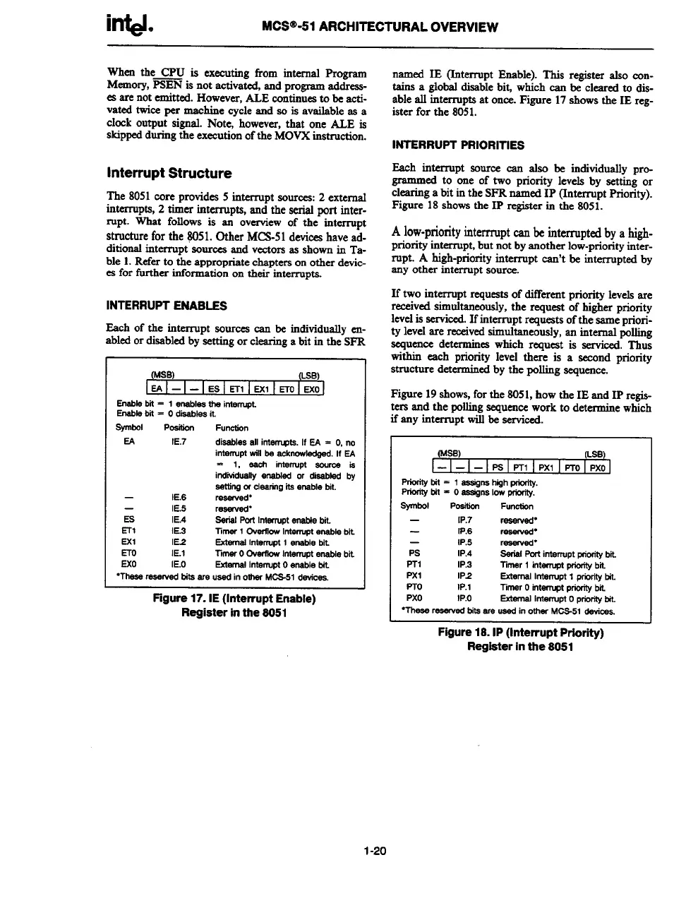
INTERRUPT PRIORITIES
Each interrupt source can also be individually pro-
~ed t? one of two
priority levels by setting or
clearing a blt m the SFR named 1P (Interrupt Priority).
Figure 18 shows the 1P register in the 8051.
A low-priority interrupt w be interrupted
bya high-
priority interrupt, but not by another low-priority inter-
IUpt. A high-priority
interruptcan’tbeinterruptedby
any other interrupt source.
If two interrupt rquests of different priority levels are
received simultaneously, the request of Klgher priority
level is serviced. If interrupt requests of the same prior-
itylevel are received simultaneously, an interred polling
sequence determines which request is serviced. Thus
within each priority level there is a second priority
structure determined by the polling sequence.
Figure 19 shows, for the 8051, how the IE and IP regie-
ters and the polling sequence work to determine which
if any inttipt Wiilbe-serviced.
(MSB)
(LSB)
——
—
IPSIPTI IPXIIPTOIPXO
Prforifybit=lsssign shighpriwity.
Prioritytit = OassignslowprWity.
symbol
POeitiQn
Functfon
—
IP.7
resewed”
IP.6
rewed”
—
IP.5 reserved-
Ps IP.4
SerialPorfinterruptp+eritybii
PTl IP.3 Timer1 intenuptpfbritybfi.
Pxl
IP2
ExternalIntenupt1 ptirity bit.
PTo
lP.1
limsr Ointerruptpriorftybii
Pxo fP.o
ExternalIntellupto priorityMt.
“Theseresewedtits are usedin otherMCB-51devices.
Figure 18. 1P (Interrupt Priority)
Register in the 8051
1-20