intd.
HARDWARE DESCRIPTION OFTHE 8051,8052 AND 80C51
Vcc
Vv,,
270252-6
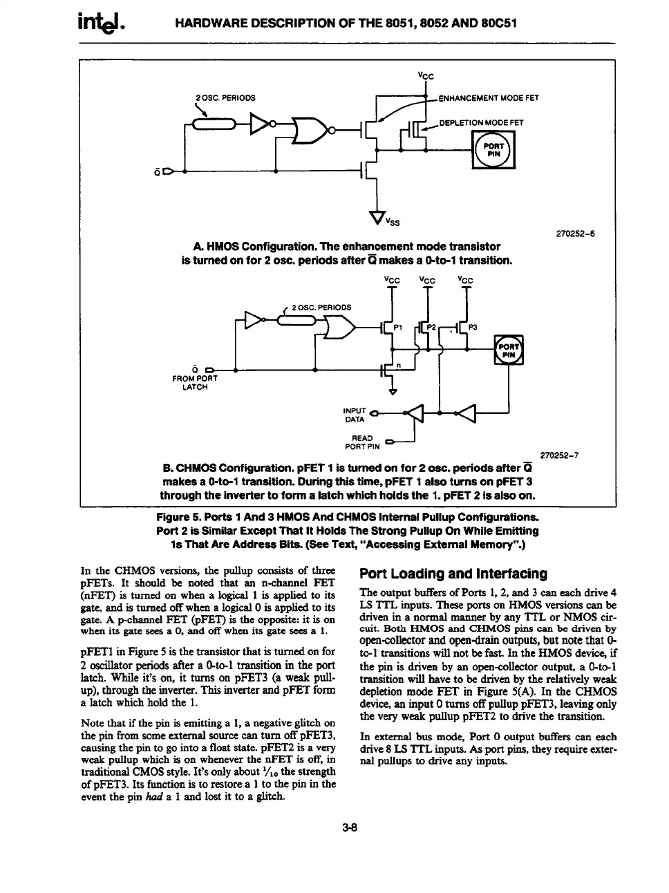
A.
HMOS Configuration. The enhancement mode transistor
is turned on for 2 OSC.periods after~ makes a O-to-1transition.
‘JCc
WC %c
2 OSC.PERIODS
PI
b
1’- ‘
6
D
n
FROMPORT
LATCH
=-’@-’@
“AD D-J
PORTPIN
270262-7
B. CHMOS Configuration. pFET 1 is turned on for 2 OSC.periods after~
makes a O-to-1transition. Duringthis time, pFET 1 also turns on pFET 3
through the inverter to form a latch whioh holds the 1. pFET 2 is also on.
Figure 5. Porta 1 And 3 HMOS And CHMOS Internal Pullup Configurations.
Port 2 is Similar Exoept That It Holds The Strong Pullup On While Emitting
1s That Are Address Bits. (See Text, “Acceaaing External Memory”.)
In the CHMOSversions,the pullup consists of three
DFETs. It shordd be noted that an n-channel FET
@ET) is turned on wherea logical1 is appliedto its
gate,and is turned offwhena logicalOis appliedto its
gate.A p-channelFET (pFET)is the opposite:it is on
whenits gate seesa O,and offwhenits gate seesa 1.
pFETl inFigure5is the transistorthat is turned onfor
2 oscillatorperiodsafter a O-to-1transition in the port
latch. While it’s on, it turns on PFET3(a weakpull-
UP),throughthe inverter.Thisinverterand pFET form
a latch whichholdthe 1.
Note that if the pinis emittinga 1,a negativeglitchon
the pinfromsomeexternalsourceean turn offPFET3,
causingthe pinto gointo a floatstate. pFET2is a very
weakpullupwhichis on wheneverthe nFET is off,in
traditionalCMOSstyle.It’sonlyabout‘/10the strength
ofpFET3.Its functionis to restorea 1to the pinin the
eventthe pin had a 1and lost it to a glitch.
Port
Loadingand Interfacing
Theoutput buffersofPorta 1,2, and 3ean each drive4
LSTTL inputs. Theseportaon HMOSversionscan be
drivenin a normal mannerby any ITL or NMOScir-
enit. Both HMOS and CHMOS
@lS can be dliVell by
open-collectorand open-drainoutputs,but note that O-
to-1transitionswillnot befast. In the HMOSdevi~ if
the pin is driven by an open-cdleetor output, a O-to-1
transitionwill have to be drivenby the relativelyweak
depletionmode FET in Figure 5(A). In the CHMOS
device,sssinput OtllmSOffpldklppFET3,kwislg
Only
the very weak
pulluppFET2to drivethe transition.
In external bus mode, Port Ooutput buffers can each
drive8L3ITL inputs.Asport pins,theyrequireexter-
nal pultupsto drive any inputs.
3-8