EasyManua.ls Logo

Intel MCS 51 User Manual

Intel MCS 51
334 pages
To Next Page IconTo Next Page
To Previous Page IconTo Previous Page
Page #49 background imageLoading...
Page #49 background image
i~e
McS@-51PROGRAMMER’SGUIDE AND INSTRUCTION SET
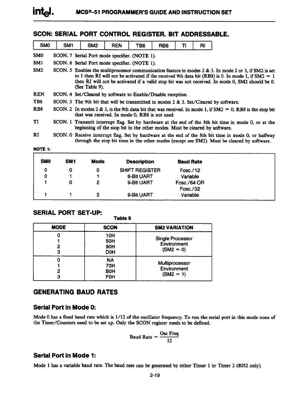
SCON: SERIAL PORT CONTROL REGISTER. BIT ADDRESSABLE.
I
SMO SM1 SM2 REN
TB8
RB8
TI
RI
SMO SCON.7
SM1 SCON.6
SM2
SCON.5
REN SCON.4
TB8 SCON.3
RB8 SCON.2
TI SCON.1
RI SCON.O
NOTE1:
SerialPort modespecifier.(NOTE 1).
Enablesthe multiproceaso
r eomrnunieationfeaturein modes2 & 3.In mode2 or 3,if SM2is set
to 1then RI willnotbe activated if the -veal 9th data bit (RB8)is O.In mode 1,ifSM2 = 1
then RI willnot be activatedif a validstop bit wasnot received.In modeO,SM2shouldbe O.
(SeeTable 9).
Set/Cleared bysoftwareto Enable/Disablereeeption.
The 9th bit that willbe transmitted in modes2 &3. Set/Cleared by software,
In modes2& 3,is the 9th data bit that wasreceived.In mode 1,ifSM2 = O,RB8is the stopbit
that wasreceived.In modeO,RB8is not used.
Transmit interrupt tlag. Set by hardware at the end of the 8th bit time in mode O,or at the
beginningofthe stopbit in the other modes.Mustbe cleared by software.
Receiveinterrupt flag. Set by hardware at the end of the 8th bit time in mode O,or halfway
through the stopbit time in the other modes(exceptsee SM2).Must be clearedby software.
SMO
SM1
Mode
Deaoription
Saud Rate
o 0 0 SHl~ REGISTER
FOSC.112
o
1
1
8-BitUART
Variable
1
0 2 9-BitUART
Fo.sc./64OR
Fosc./32
1
1
3
9-BitUART
Variable
SERIAL PORT SET-UP:
Table 9
MODE
SCON SM2 VARIATION
o 10H
1 50H
SingleProcessor
2 90H
Environment
3 DOH
(SM2 = O)
o
1
:0;
Multiprocessor
2 BOH
Environment
3
FOH
(SM2 = 1)
GENERATING BAUD RATES
Serial Port in Mode O:
ModeOhasa freedbaud rate whichis 1/12of the oscillatorfrequency.To run the serial port in this modenoneof
the Timer/Countersneed to be
setup. Only the SCONregisterneedsto be defined.
BaudRate = Y
Serial Port in Mode 1:
Mode 1hss a variablebaud rate. The baud rate can be generatedbyeither Timer 1or Timer 2 (8052only).
2-19

Table of Contents

Question and Answer IconNeed help?

Do you have a question about the Intel MCS 51 and is the answer not in the manual?

Intel MCS 51 Specifications

General IconGeneral
Architecture8-bit
Number of Instructions111
Clock Speed12 MHz
Register Size8-bit
Internal RAM128 bytes
Internal ROM4 KB
External Memory64 KB
I/O Pins32
Timers2
Serial Port1
Interrupts5
Operating Voltage5V
UARTYes
Program Memory4 KB
RAM128 bytes
Instruction SetCISC

Summary

MCS® 51 Family of Microcontrollers Architectural Overview

THE MCS®-51 INSTRUCTION SET

Provides an overview of the MCS®-51 instruction set, optimized for 8-bit control applications.

Interrupt Structure

Overview of the 8051 interrupt structure, sources, and vectoring.

MCS® 51 Programmer’s Guide and Instruction Set

MCS®-51 INSTRUCTION SET

Provides a summary of the 8051 instruction set, including mnemonics and operands.

8051, 8052 and 80C51 Hardware Description

TIMER/COUNTERS

Describes Timer 0 and Timer 1, including operating modes and control registers.

8XC52/54/58 Hardware Description

8XC51FX Hardware Description

PORT STRUCTURES AND OPERATION

Details port structures, I/O configurations, and external memory access.

SERIAL INTERFACE

Covers serial port modes, framing error detection, and baud rate generation.

87C51GB Hardware Description

SPECIAL FUNCTION REGISTERS

Provides a map of the SFR space and their reset values.

SERIAL PORT

Details the serial port's modes, framing error detection, and baud rates.

INTERRUPTS

Covers interrupt sources, enable registers, and priority levels.

83C152 HARDWARE DESCRIPTION

Related product manuals