in~.
8XC51FXHARDWAREDESCRIPTION
- 16 BITS EACH +
P1.3/CEXO
P1.4/cExl
— 16 BIT6 —
PI .5/cEx2
P1.6/CEX3
PI .7/cEx4
270653-12
Figure 15a. Programmable Counter Array
The PCA timer/counter and compare/captore modules
sharePort 1 pinsfor external I/O. These pins arelisted
below. If the port pin is not used for the PCA, it cars
still be used for standard I/O.
PCA Component
External 1/0 Pin
16-bit
Counter P1.2I ECI
16-bitModuleO
P1.3/ CEXO
16-bitModule1 PI.41 CEX1
16-bitModule2
P1.5/
CEX2
16-bitModule3 P1.6/ CEX3
16-bitModule4
P1.7I CEX4
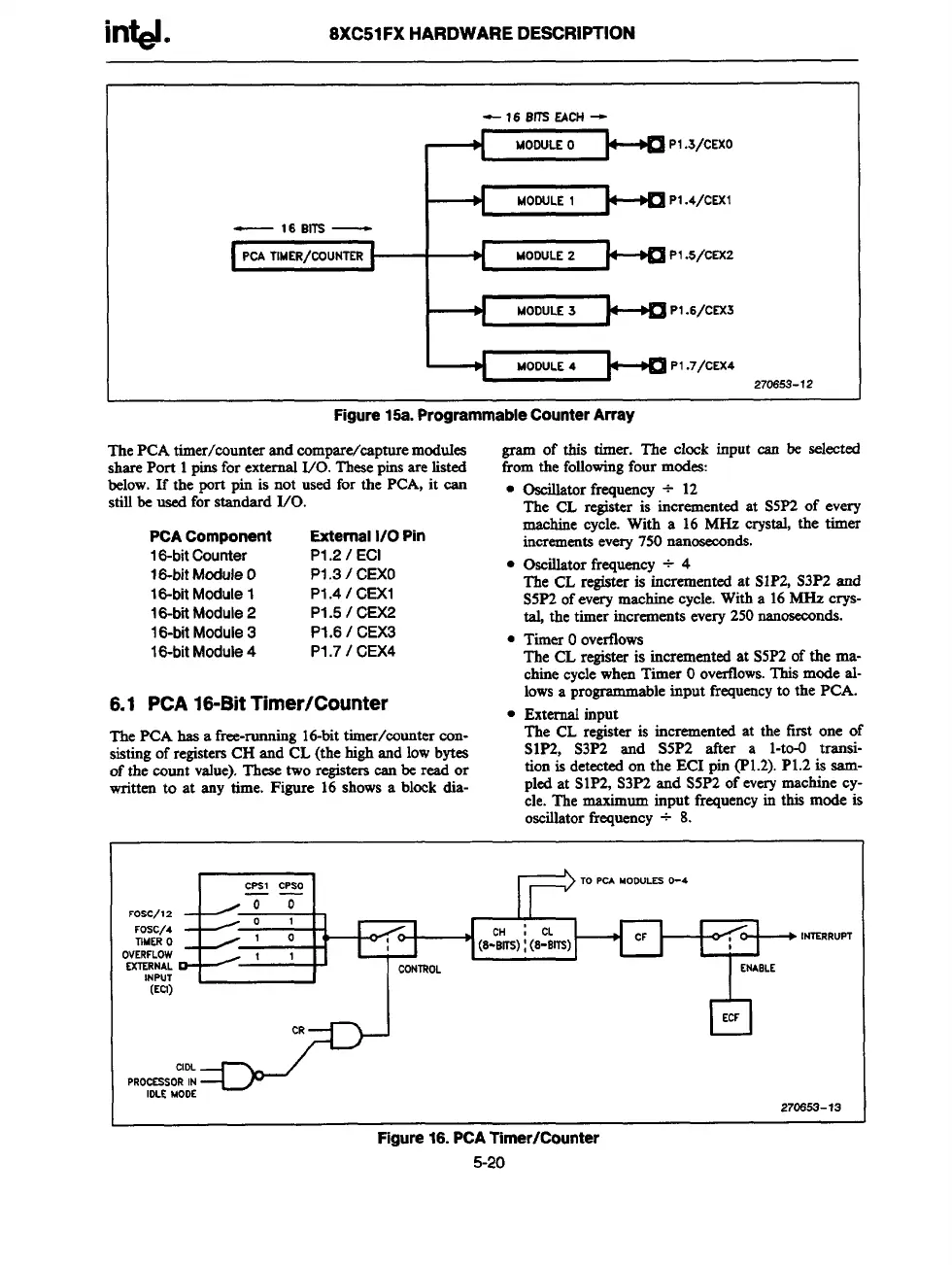
6.1 PCA 16-BitTimer/Counter
gram of this timer. The clock input can bc selected
from the following four modes:
● Oscillatorfrequency + 12
The CL register is incremented at S5P2 of every
machine cycle. With a 16 MHz crystal, the timer
increments every 750 mmoseco
rids.
● Oscillatorfrequency + 4
The CL registeris incremented at S1P2, S3P2 and
S5P2 of every machine cycle. With a 16 MHz crys-
tal, the timer increments every 250 nanoseconds.
● Timer Oovertlows
The CL registeris incremented at S5P2 of the ma-
chine cycle when Timer Ooverfiows.This mode al-
lows a programmableinput frequencyto the PCA.
. External input
The PCA has a free-running 16-bittimer/counter con-
The CL re~ster is incremented at the first one of
sisting of registersCH and CL (the high and low bytea
S1P2, S3P2 and S5P2 after a l-to-O transi-
of the count value). These two registerscan be read or
tion is detected on the ECI pin (P1.2). P1.2 is aam-
written to at any time. Figure 16 shows a block dia-
pled at S1P2, S3P2 and S5P2 of everymachine cy-
cle. The maximum input frequencyin this mode is
oscillatorfrequency ~ 8.
FOsc/12
FOSC/4
TIMER O
OVERFLOW
EXTERNAL
tNPUT
(Eel)
CPS1 cPsO
TO PCA MoOULES O-4
——
00
/
01
1<
,
1
1
P -
CONTROL
lb
ENASLE
L
I
I
I
XJ
CR
n
ECF
. INTERRuPT
270663-13
Figure16.PCA Timer/Counter
5-20