in~.
HARDWARE DESCRIPTION OF THE 8051,8052 AND 80C51
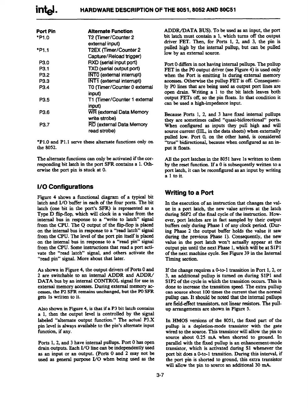
Port Pin Alternate Function
“P1.o T2
(Timer/Counter2
externalinput)
*P1.1 T2EX(Timer/Counter2
Capture/Reloadtrigger)
P3.O RXD (serialinputport)
P3.1
TXD (serialoutputport)
P3.2
INTO(externalinterrupt)
P3.3
~ (externalinterrupt)
P3.4
TO(Timer/CounterOexternal
input)
P3.5
T1 (Timer/CounterI external
input)
P3.6
~ (externalData Memory
write
strobe)
P3.7
~
(external DataMemory
readstrobe)
●P1.Oand P1.1serve these aftemate fuctions onlyon
the 8052.
The alternatefunctionscan onlybe activatedif the cor-
respondingbit latch in the pm-tSFRcontainsa 1.0th-
erwisethe port pinis stuck at O.
1/0 Configurations
Figure 4 showsa fictional diagram of a typical bit
latch and 1/0 bufferin each of the four ports.The bit
latch (one bit its the port’s SFR) is representedas a
TypeD tlipflop, which will clock in a valuefrom the
internal bus in response to a “write to latch” signal
from the CPU.The Q output of the tlipflop is placed
on the intersttdbusitsresponseto a “read latch” signal
from the CPU.The levelof the port pin itselfis placed
on the internal bus in responseto a “read pin” signal
fromthe CPU.Someinstructionsthat read a port acti-
vate the “read latch” signal, and others activate the
“read pin” signal.More about that later.
As shownin Figure4, the outputdriversof PortsOand
2 are switchableto an istternrdADDR and ADDR/
DATA busbyan internal CONTROLsignalfor w its
externalmemoryaccesam.
Duringexternalmemoryac-
cesses,the P2SFRrcsrm
“nsunchanged,but the POSFR
gets 1swritten to it.
Nso showninFigure4, isthat ifa P3bit latchcontains
a 1, then the output level is controlledby the signal
labeled “alternate output function.” The actual P3.X
pin levelis afwaysavailableto the pin’salternate input
function,if any.
Ports 1,2, and 3haveinternal puUups.Port Ohas open
drain outputs.EachI/O lineeanbe independentlyused
as an input or an output. (Ports Oand 2 may not be
used as generalpurpose I/O whetsbeing used as the
ADDIVDATABUS).To be usedas an input, the port
bit latch must contain a 1,whichturns off the output
driver FBT. Then, for Ports 1, 2, and 3, the pin is
pulledhigh by the internal puflup,but can be pulfed
lowby an externalsource.
Port Odiffersinnot havinginternsdpullups.Theptiup
FBTin the POoutputdriver(seeFigure4) is usedonfy
when the Port is ernitdng 1sduringexternal memory
accasea otherwise
the pullupFET is off.Conaequent-
IyPOlima that are beingusedas output port linesare
open drain. Writing a 1 to the bit latch leaves both
output FETs off, so the pin floats.In that conditionit
can be used a high-impedanceinput.
BecausePorts 1, 2, and 3 have fixedinternaf pullups
they are sometimescalled “qussi-bidirectional”porta.
Whets eontigured as inputs they pull high and will
sourcecurrent (IIL, in the data sheets)whenextemafly
pulled low. Port O,on the other hand, is considered
“true” bidirectional,becausewheneont@red as an in-
put it floats.
Affthe port latchesitsthe 8051have 1swritten to them
bythe resetfunction.If a Oissubsequentlywritten to a
port latch, it canbe reconfiguredas an input bywriting
a 1to it.
Writingto a Port
In the executionof an instructionthat changesthe val-
ue in a port latch, the newvalue arrives at the latch
duringS6P2of the final cycleof the instruction. How-
ever, port latches are in fact sampledby their output
buffers
O~Y during Phase 1of SSlyclockperiod. @IK-
ittg Phase 2 the output buffer holds the value it saw
during the previousPhase 1). Consequently,the new
value in the port latch won’t actually appear at the
outputpin untilthe nextPhase1,whichwillbeat SIP1
ofthe nextmachinecycle.SeeFigure39in the Internal
Timingsection.
If thechangerequiresa O-to-1transitionin Port 1,2, or
3, art additionalpullup is turned on during SIP1 and
S1P2ofthe cyclein whichthe transitionocmu-s..Thisis
doneto increasethe transitionspeed.The extra pullup
can sourceabout 100timesthe currentthat the normal
pullupcan. It shouldbe notedthat the internal pttllups
are field-effecttransistors,notlinearresistors.Tlseptdl-
up
-CInCntS are shownin Figure5.
In HMOSveraionsof the 8051,the fixed part of the
pullup is a depletion-modetransistor with the gate
wiredto the source.Thistransistorwillallowthe pin
to
source about 0.25 mA when shorted to ground. In
parallelwith the fixedpullupis assenhancement-mode
transistor, which is activatedduring S1 wheneverthe
port bit doesa O-to-1transition.Duringthis intervaf,if
the port pin is shorted to ground,this extra transistor
willallowthe pin to sourcean additional30sttA.
3-7