i@.
8XC52/54/58 HARDWARE DESCRIPTION
with OFFHleaves the byte unchanged,leaving the En-
cryption Array unprogrammed in effect bypasses the
encryption festure.
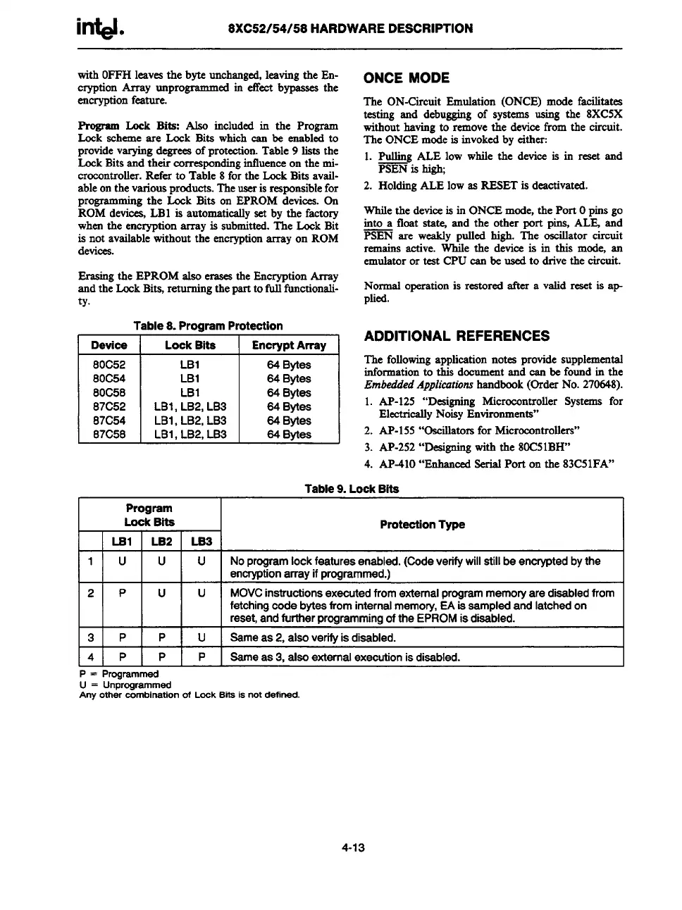
e Lock Bits: Also included in the Program
Lock scheme are Lock Bits which can be enabled to
providevarying degreeaof protection. Table 9 lists the
Lock Bits and their correspondinginfluence on the mic-
rocontroller. Refer to Table 8 for the Lock Bits avsil-
ableon the variousproducts. The useris responsiblefor
programming the Lock Bits on EPROM devices. On
ROM deviwsi, LB1 is automatically set by the factory
when the encryption array is submitted. The Lock Bit
is not availablewithout the encryptionarrayon ROM
devices.
Erasing the EPROM also
erasesthe Encryption Array
and the Lock Bits, returning thepartto tldl functionali-
ty.
Table 8. Program Protection
Devioe Lock Bits Encrypt Array
80C52
LB1 84 Bytes
80C54
LB1 84 Bytes
80C58
LB1 84 Bytes
87C52
LB1, LB2, LB3 84 Bytee
87C54
LB1, LB2, LB3
64 Bytes
87C58
LB1, LB2, LB3 84 Bytes
ONCE MODE
The
ON-Circuit Emulation (ONCE) mode facilitates
testing and debugging of systems using the 8XC5X
without having to remove the device from the circuit.
The ONCE mode is invoked by either:
1. _ ALE low while the device is in reset and
PSEN is high;
2. Holding ALE low as RESET is deactivated.
While the device is in ONCE mode, the Port Opins go
into a float state and the other port pins, ALE and
PSEN are weakly pulled high. The oscillator circuit
remains active. While the device is in this mode, an
emulator or test CPU can be used to drive the circuit.
Normal operation is restored after a valid reset is ap
plied.
ADDITIONAL REFERENCES
The
followingapplication notes provide supplemental
informationto this document and can be found in the
EmbeddedApplicatwnshandbook (OrderNo. 270648).
1. AP-125 “Designing Microcontroller Systems for
ElectricallyNoisy Environments”
2. AP-155 “Oscillatorsfor Microcontrollers”
3. AP-252“Deaigning with the 80C51BH”
4. AP-41O“Enhanced serial Port on the 83C51FA”
Table9.LockBits
I
Program
I
I
LockBite
Protection
Type
LBl
LB2 LB3
1
u
P
u
u
u
-u-
Noprogramlockfeaturesenabled.(Codeverifywillstillbeencryptedbythe
encryptionarrayifprogrammed.)
MOVCinstructionsexecutedfromexternalprogrammemoryaredisabledfrom
fetchingcodebytesfrominternalmemory,EAissampledandlatchedon
reset,andfurtherprogrammingoftheEPROMisdisabled.
I 3 I P I P I U I Bameas2.alsoverifvisdisabled.
I
4
P P P Bameas3, alsoexternalexecutionisdisabled.
P = Programmed
U = Unprogrammed
Any other combination of Lock Bits is not defined.
4-13