i~o
8XC51FXHARDWAREDESCRIPTION
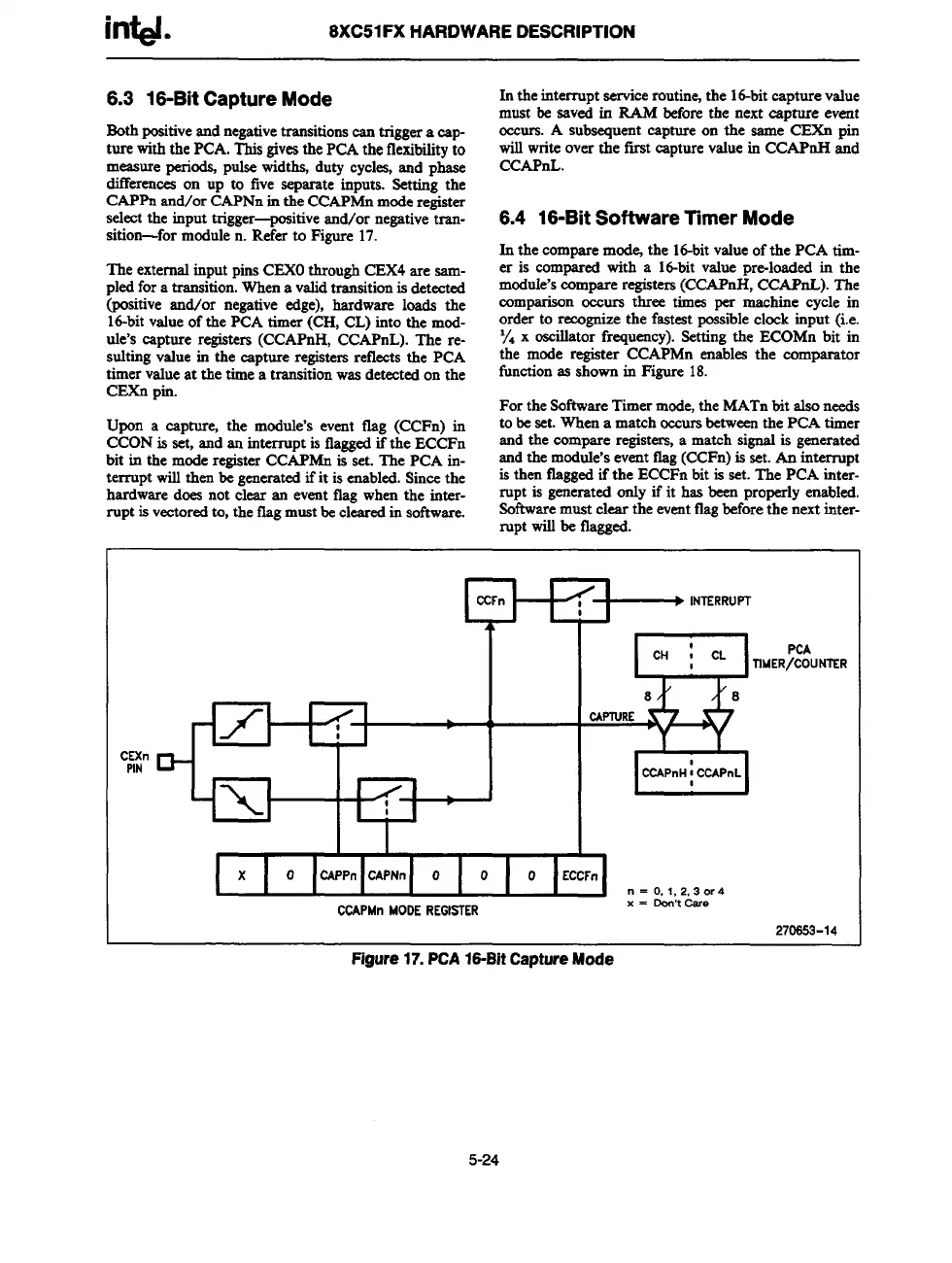
6.3 16-Bit Capture Mode
Bothpositiveandnegativetransitionseantriggeracap-
turewiththe
PCA. This gives the PCA the flexibility to
measure perio& pulse widths, duty cycles, and phase
differences on up to five separate inputs. Setting the
CAPPn snd/or CAPNn in the CCAPMn mode register
select the input trigger-positive snd/or negative tran-
sition-for module n. Refer to Figure 17.
The externalinput pins CEXOthrough CEX4 aresam-
pled fora transition.When a validtransitionis detected
(psitive rind/or negativeedge),hardware loads the
16-bitvrdueof the PCA timer (CH, CL) into the mod-
de’s capture registers(CCAPnH, CCAPnL). The re-
sulting value in the capture registersreflects the PCA
timer value at the time a transitionwas detected on the
CEXn pin.
Upon a capture, the module’s event flag (CCFn) in
CCON is set, and an interruptis flaggedif the ECCFn
bit in the mode regista CCAPMn is set. The PCA in-
terruptwill then be generatedifit is enabled. Since the
hardwaredoes not clear an event tlag when the inter-
rupt is vectoredto, the tlag must be clearedin software.
In the interruptservice routine,the lt%it capturevalue
must be saved in IL4M before the next capture
event
ocours.
A subsequent capture on the same CEXn pin
will write over the first capturevalue in CCAPnH and
CCAPnL.
6.4 16-Bit Software Timer Mode
In
the eotnparemodej the 16-bitvalue of the PCA tim-
er is compared with a 16-bit value pm-loaded in the
module’scompare registers(CCAPnH, CCAPnL). The
comparison oeours three times per machine cycle in
order to recognize the fastest possible clock input (i.e.
~. x oscillator frequency). Setting the ECOMn bit in
the mode register CCAPMn enables the comparator
function as shown in Figure 18.
For the SoftwareTimermode, the MATn bit also needs
to be set. When a match occursbetween the PCA timer
and the compare registen, a match signal is generated
and the module’s event flag (CCFn) is set. An interrupt
is then flagged if the ECCFn bit is set. The PCA inter-
rupt is generated ordy if it has been properly enabled.
software must clear the eventflagbefore the next inter-
rupt will be flagged.
——
+-l
1/1
1
I
CEXn&
PIN
+KJ
I /1
I
I
I
+-’N”RRUM
z
CH : CL
PCA
I
llMER/COUNIER
8 8
CAPTURE
GGl
I I I
I
x
I
o
I
o
I
o ECCFn
n = O,1, 2, 3 or
4
CCAPMnMOOEREGISTER
x = OOtrt Care
270653-14
Figure 17. PCA16-Bit Capture Mode
5-24