i~.
8XC51FXHARDWAREDESCRIPTION
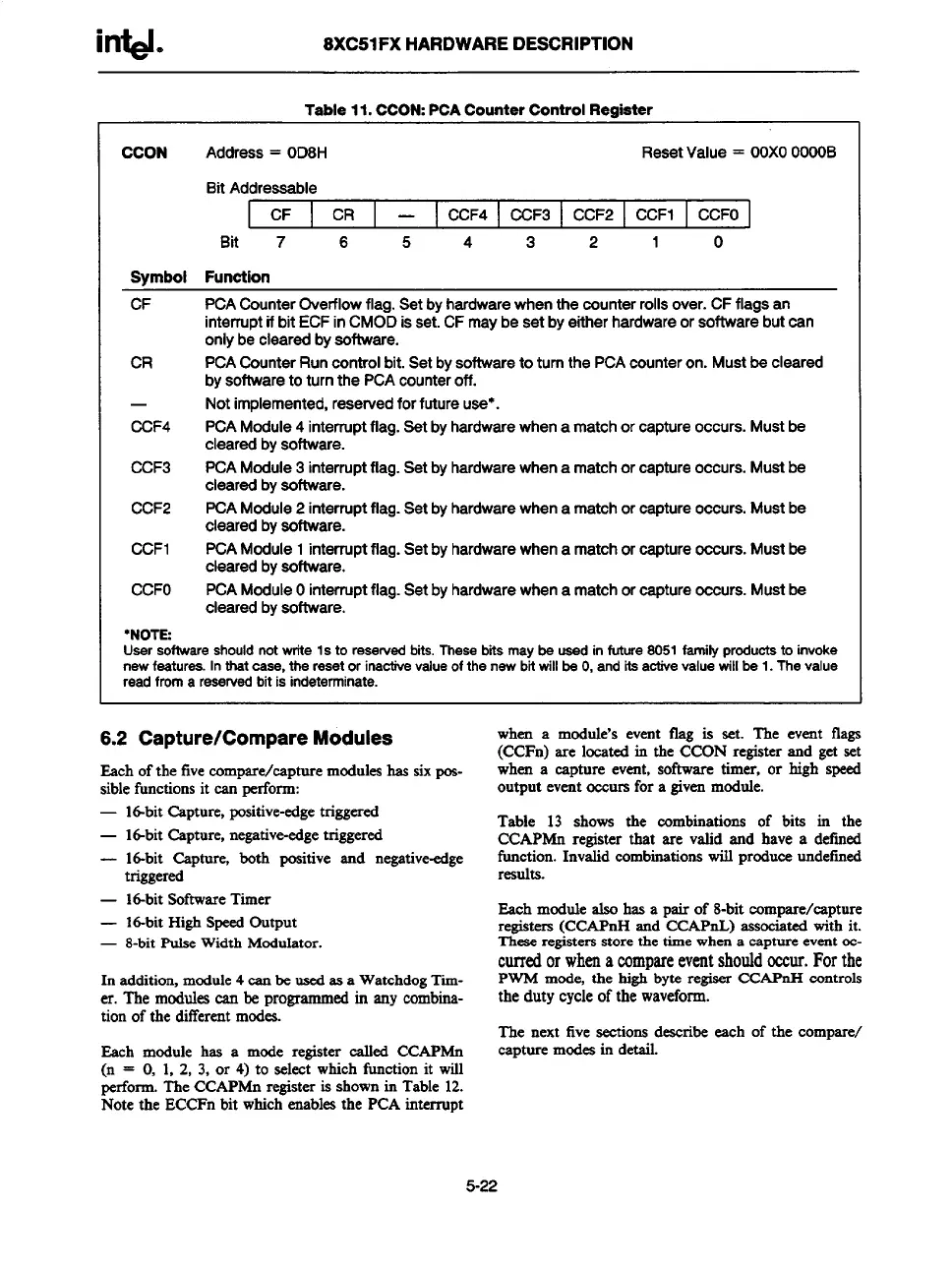
Table 11. CCON:PCA Counter Control Register
CCON
Address= OD8H
ResetValue= OOXOOOOOB
BitAddressable
I
CF CR —
CCF4 CCF3 CCF2 CCF1
CCFO
Bit 7 6 5 4 3 2
1
0
Symbol Function
CF
CR
—
CCF4
CCF3
CCF2
CCF1
CCFO
PCACounterOverflowflag.Setbyhardwarewhenthecounterrollsover.CFflagsan
interruptif bit ECFinCMODisset.CFmaybesetbyeitherhardwareorsoftwarebutcan
onlybeclearedbysoftware.
PCACounterRun
control bit. Set by software to turnthePCAcounteron.Mustbecleared
bysoftwareto turnthe PCAcounteroff.
Notimplemented,reservedforfutureuse”.
PCAModule4 interruptflag.Setbyhardwarewhenamatchorcaptureoccurs.Mustbe
clearedbysoftware.
PCAModule3interruptflag.Setbyhardwarewhena matchorcaptureoccurs.Mustbe
clearedbysoftware.
PCAModule2 interruptflag.Setbyhardwarewhenamatchorcaptureoccurs.Mustbe
clearedbysoftware.
PCAModule1interruptflag.Setbyhardwarewhena matchorcaptureoccurs.Mustbe
clearedbyeoftware.
PCAModuleOinterruptflag.Setbyhardwarewhena matchorcaptureocours.Mustbe
clearedbysoftware.
UsersoftwareshouldnotwriteIs toresend bits,Thesebitsmaybeusedinfuture8051familyproductsto
invoke
new features.
In that case, the reset or inaotive value of the new bit will be O, and its active value willbe 1. The value
read from a reserved bit is indeterminate.
Each of the five compare/capture modules has six pos-
sible functions it can perform:
— Id-bit Capture, positive-edge triggered
— l~bit Capture, negative-edgetriggered
— 16-bit Capture, both positive and negative-edge
triggered
— 16-bitSoftwareTimer
— 16-bit High Speed Output
— 8-bit pulse Width
Modulator.
In addition, module 4 can be used as a WatchdogTime-
r. Themodulescanbeprogrammedinsnycombina-
tion of the differentmodes.
Each module has s mode register called CCAPMn
(n = O, 1, 2, 3, or 4) to select which fimction it will
perform. The CCAPMn registeris shown in Table 12.
Note the ECCFn bit which enables the PCA interrupt
6.2 Capture/Compare Modules
when a module’s event flag is set. The event flags
(CCFn) are located in the CCON register and get set
when a capture event, software timer, or high speed
outputevtit occurs for a given module. - -
Table 13 shows the combinations of bits in the
CCAPMn register that are valid and have a defined
function. Invalid combinations will produce undefined
results.
Each module also has a pair of 8-bit compsre/capture
registers (CCAPnH and CCAPnL) associated with it.
These
registers store the time when a capture event oc-
curredorwhenacompareeventshouldoccur.Forthe
PWM mode, the high byte regiser CCAPnH controls
the duty cycle of the wsveform.
The next five sections describe each of the compare/
capture modes in detail.
5-22