i~m
8XC52/54/58 HARDWARE DESCRIPTION
I
Osc
l-l
TL2 : TH2
1
1
● (S.-Blt$) :(S-Bite)
I
I
TR2
)
Cfi Bit
P1.o
1 I* I
(T2)
I
+2
}
1
I
a
1
~T&%:n
T20E (T!2MO0.1)
P1.1
1<1
(’22X)
I
EXF2
I
Timer 2
I
‘ Interrupt
I
EX~N2
270783-6
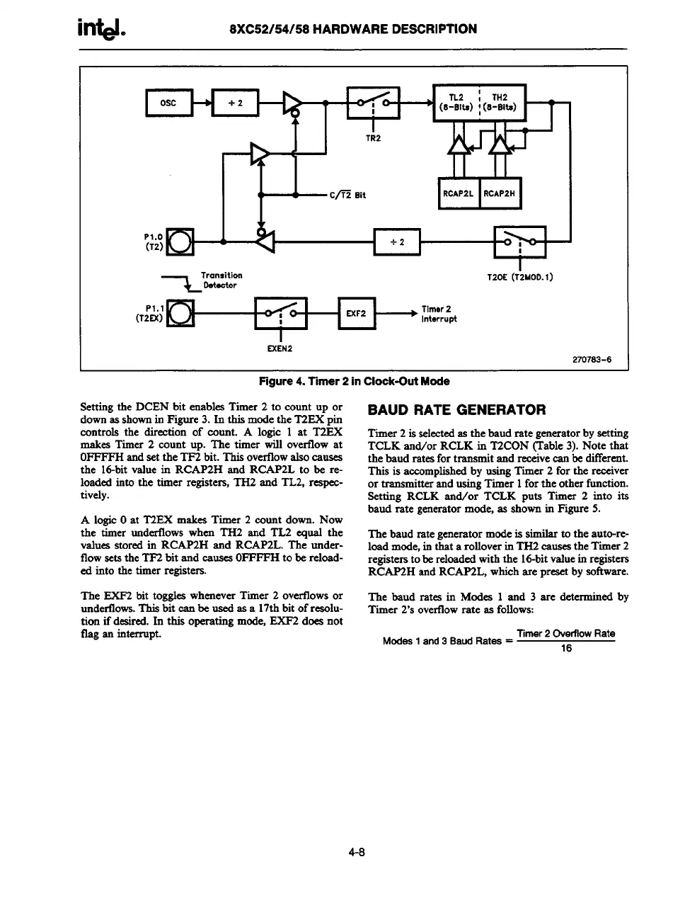
Figure 4. Timer 2 in Clock-Out Mode
Setting the DCEN bit enables Timer 2 to count up or
down as shown in Figure 3. In this mode the T2EX pin
controls the direetion of count. A logic 1 at T2EX
makes Timer 2 count up. The timer will overflow at
OFFFFHand set the TF2 bit. This overtlowalso causes
the 16-bit value in RCAP2H and RCAP2L to be re-
loaded into the timer registers, TH2 and TL2, respec-
tively.
A logic Oat T2EX makes Timer 2 count down. Now
the timer underfiows when TH2 and TL2 equal the
values stored in RCAP2H and RCAP2L. The rmder-
flow sets the TF2 bit and causes OFFFFHto be reload-
ed into the timer registers.
The EXF2 bit toggles whenever Timer 2 overtlows or
undertows. This bit ean be used as a 17thbit of resolu-
tion ifdeaired. In this operating mode, EXF2 does not
flag an interrupt.
BAUD RATE GENERATOR
Timer 2 is selectedas the baud rategeneratorby setting
TCLK and/or RCLK in T2CON (Table 3). Note that
the baud ratesfor transmit and receivecan be different.
This is accomplished by using Timer 2 for the receiver
or transmitterand using Timer 1forthe otherfunction.
Setting RCLK rind/or TCLK puts Timer 2 into its
baud rate generatormode, as shown in Figure 5.
The baud rategeneratormode is similar to the auto-re-
load mod%in thata rolloverin TH2 causesthe Timer2
registersto be reloadedwith the id-bit vrduein registers
RCAP2H and RCAP2L, which are presetby software.
The baud rates in Modes 1 and 3 are determined by
Timer 2’s overtlowrate as follows:
Modea 1 and 3 Baud Ratea =
Timer2 Overflow Rate
16
4-8