intd.
MCS@-51 ARCHITECTURAL OVERVIEW
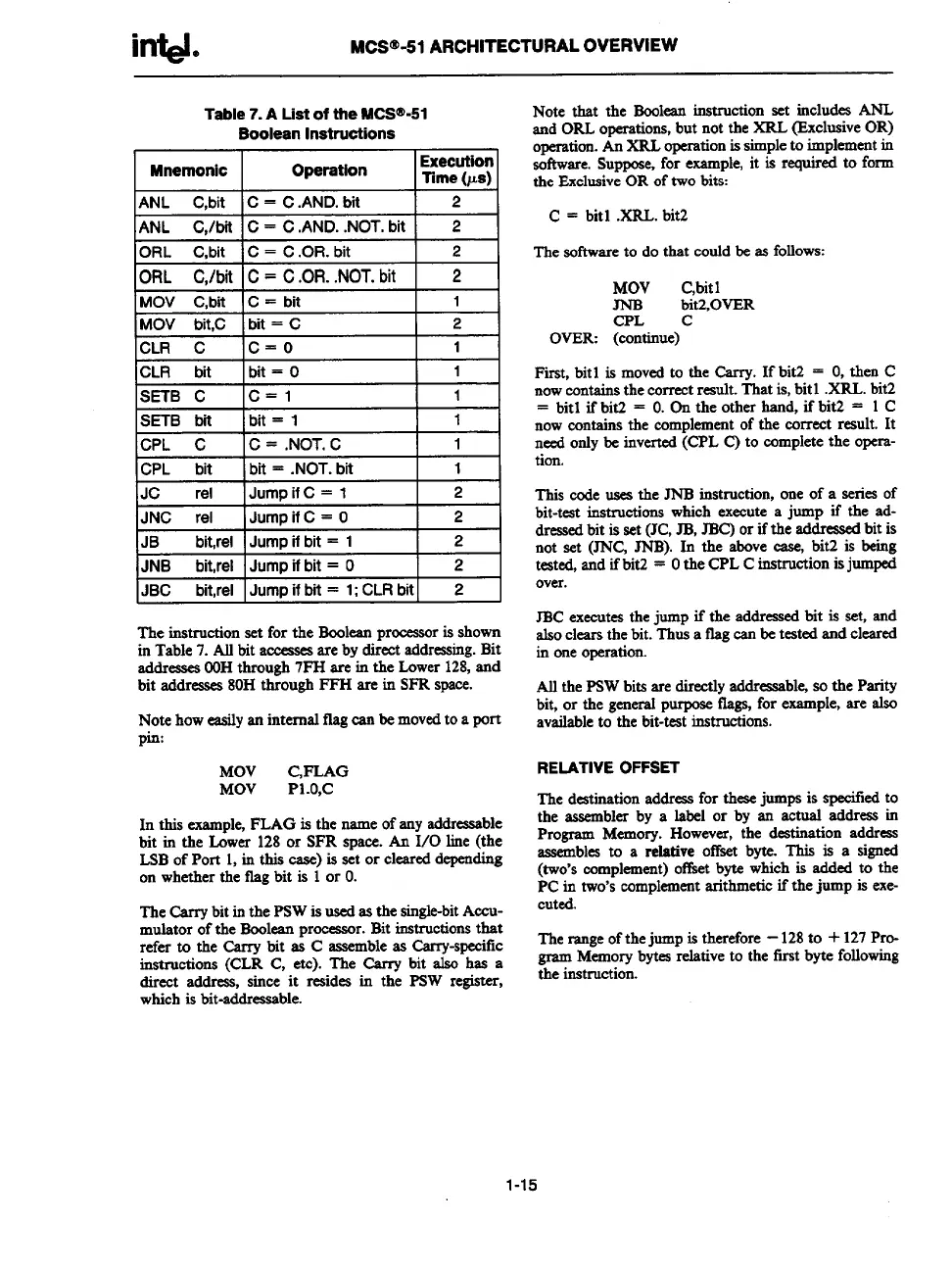
Table
7. A List of the MCS’@-51
Boolean Instrutilons
Mnemonic
Operation
Execution
Time (us)
ANL C,bit IC = C .AND. bit
I
2
ANL C./bit !C = C .AND. .NOT. bit I 2
I 1
nnl
n G.
16= C.OR. bit 2
F
MO\
MO\ UIL,U
I UIL – w
1= I
ICLR c
Ic=o
1
1
CLR bit
]bit=o
1
SETB C
Ic=l
I
1
SETB bn Ibit= 1 1
CPL C IC = .NOT. C
1
CPL bit Ibit = .NOT. bit
1
JC
rel
lJumpif C= 1
2
JNC rel Jump if C = O
2
JB bit,rel
Jump if bti = 1
2
JNB bit,rel Jump if bit = O
2
JBC bit,rel IJump if bti = 1; CLR bit I 2
The instruction set for the Boolean processor is shown
in Table 7. Alt bit ameaaca are by direct addressing. Blt
addreases OOHthrough 7PH are in the Lower 128,and
bit addresses 80H through FFH are in SFR space.
Note how easily an internal ilag can be moved to a port
pin:
MOV C,PLAG
MOV
P1.o,c
In this example, FLAG is the name of any addressable
bit in the Lower 128 or SFR space. An 1/0 line (the
LSB of Port 1, in this case) is set or cleared depending
on whether the flag blt is 1 or O.
The bTy
bitinthePsW isused as the single-bit ACCU.
mulator of the Boolean processor. Bit instructions that
refer to the Carry bit as C assemble as Carry-specflc
instructions (CLR C, etc). The Carry bit also has a
direct addreas, since it resides in the PSW register,
which is bit-addressable.
Note that the Boolean instruction set includes ANL
and ORL operations, but not the XRL (_ExclusiveOR)
operation. An XRL operation is simple to implement in
sof?.ware.Suppose, for example, it is Wuired @ form
the Exclusive OR of two bits
C = bitl .XRL. bit2
The sot%vareto do that could be as follows:
MOV
C,bit 1
bit2,0VER
CPL C
OVER (continue)
Fkst, bit 1 is moved to the Carry. If bit2 = O,then C
now contains the correct reauh. That is, bit 1 .XRL. bit2
= bitl ifbiti = O.On the other hand, ifbit2 = 1 C
now contains the complement of the correct result. It
need only be inverted (CPL C) to complete the opcrs-
tion.
This code uses the JNB instruction, one of a series of
bk-teat instructions which execute a jump if the ad-
dressed bit is set (JC, JB, JBC) or if the addressed bit is
not set (JNG JNB). In the above case, blt2 is being
tested, and if bitZ = Othe CPL C instruction is jumped
over.
JBC executes the jump if the addressed bit is set, and
also clears the bit. Thus a fig can be teated and cleared
in one operation.
All the PSW bits are directly addressable so the Parity
bit, or the general purpose flags, for example, are also
available to the bit-test instructions.
RELATIVE OFFSET
The
destination address for these jumps is specitied to
the assembler by a label or by an actual address in
Program Memory. However, the destination address
assembles to a relative offset byte. This is a signed
(two’s complement) oftket byte which is added to the
PC in two’s complement arithmetic if the jump is exe-
cuted.
The range of the jump is therefore -128 to + 127 Pro-
gram Memory bytes relative to the first byte following
the instruction.
1-15