intd.
87C51GBHARDWAREDESCRIPTION
500
qao
x
:s00
E
z 2Ga
100
: :~
4 8
12 16
CRYSTALFREQUENCV
In MHz
270897-39
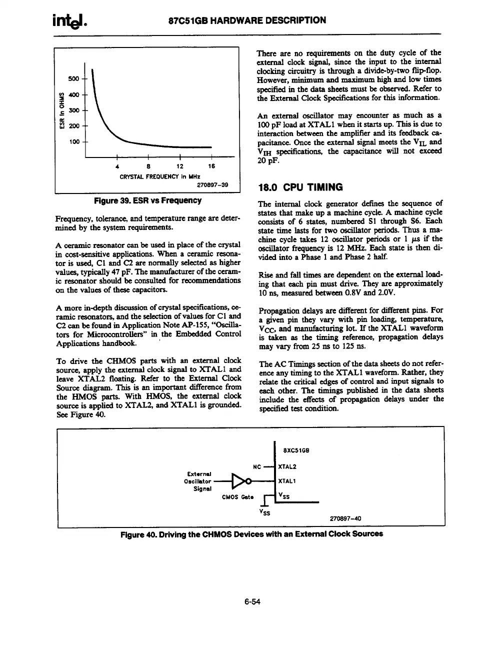
Figure39.ESRvsFrequency
.
Frequency,tolerate%andtemperaturerangeare deter-
mined by the systemrequirements.
A
ceramicresonatorcan be usedin placeofthe crystal
in cost-sensitiveapplications.when a ceramic resona-
tor is used Cl and C2 are normallyselectedas higher
values,typicslly47pF.Themanufacturerofthe ceram-
ic resonator shouldbe consultedfor recommendations
on the valuesof theaecapacitors.
A more indepth discussionofcrystalspecifications,ce-
ramic reaonatomand the selectionofvaluesfor Cl and
C2can be foundin ApplicationNote AP-155,“Oscilla-
tors for Mic
rmontrollers” in the EmbeddedControl
Applicationshandbook.
To drive the CHMOS parts with an external clock
source, apply the externalclocksignalto XTALI and
leave XTAL2 floating. Refer to the External Clock
Source diagram. This is an impmtant differencefrom
the HMOS parts. With HMOS, the external clock
sourceis appliedto XTAL2,and XTAL1is grounded.
SeeFigure 40.
There are no requirements on the duty cycle of the
external clock signal, since the input to the internal
cheking circuitry is through a divide-by-twofiipflop.
However,minimumand maximumhighand lowtimes
spsd%d in the data sheetsmustbe observed.Referto
the ExternalClockSpecificationsforthis information.
h extermd oscillator may encounteras much as a
100pF loadat XTAL1whenit starts up.Thisis due to
interactionbetweenthe amplifierand its feedbackca-
pacitance.Oncethe external signalmeetsthe VII-.and
k’~ speeiticationa,the capacitarm will not exceed
20pF.
18.0 CPUTIMING
The internal clock generator &tines the sequenceof
states that makeup a machinecycle.A machinecycle
consists of 6 ststea, numberedS1 through S6. Each
state time lasts for two oscillatorperiods.‘fIms a nta-
chine cycle takes 12 oscillator periodsor 1 ps if the
oscillatorfrequencyis 12MHs. Each state is then di-
videdinto a Phase 1and Phase2 half.
Riseand falltimes are dependentonthe externalload-
ing that each pin must drive. Theyare approximately
10n$ measuredbetween0.8Vand2.OV.
Propagationdelaysare ditkent for differentpins. For
a given pin they vary with pin loading,temperature,
V~, and manufacturinglot. If the XTAL1waveform
is taken as the timing reference,propagationdelays
mayvary fmm 25 ns to 125m.
TheACTimingssectionofthe datasheetsdonot refer-
enceanytimingto the XTAL1waveform.Rather, they
relate the critical edgesof controlandinput signalsto
each other. The timings publishedin the data sheets
include the effects of propagationdelays under the
specifiedtestcondition
-+4
8XC51GB
NC
XTAL2
Ext*rnal
Oscilidor
XTAL1
Signal
CMOS ode
Vss
Vss
270S97-40
Figure40.DrivingtheCHMOS DeviceswithanExternalClock Sources
6-54