irrtd.
HARDWARE DESCRIPTIONOF THE 8051,8052 AND 80C51
Sxlins
270252-12
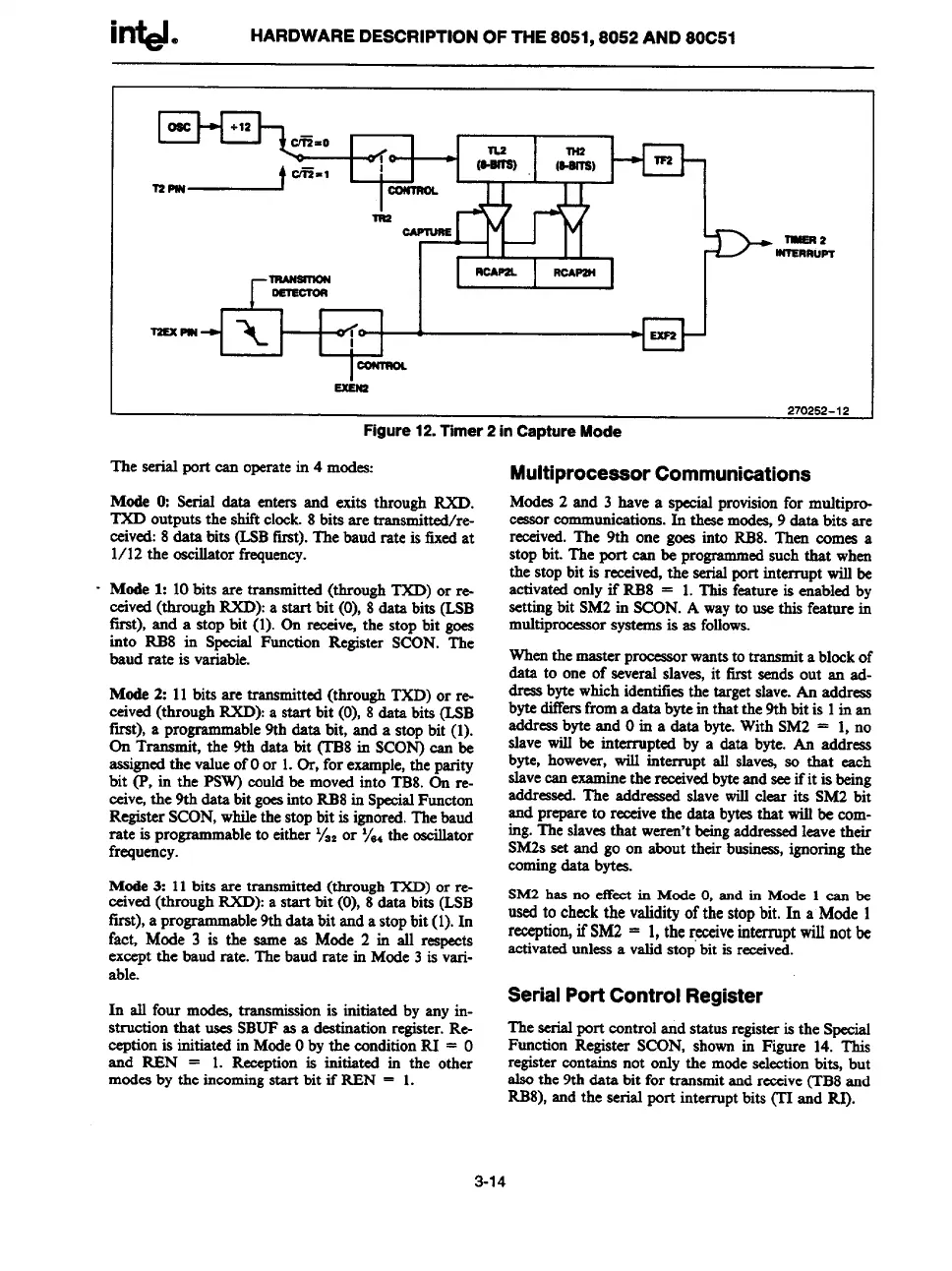
Figure
12.Timer 2 inCaptureMode
The serial port can operatein 4 modes:
Mode O:Serial date enters end exits through RXD.
TXD outputs the shiftclock.8 bits are tranamittext/re-
ceived:8date bits (LSBftrat).The baud rate is tixedat
1/12 the oscillatorfrequency.
- Mode 1: 10bits are transmitted(throughTXD) or re-
ceived(throughRXD):a start bit (0), 8data bits (LSB
first), and a stop bit (l). On receive+the stop bit goes
into RB8 in Special Function Register SCON. The
baud rate is variable.
Mode 2: 11bits are transmitted(through TXD) or re-
ceived(throughRXD):a start bit (0), 8data bits (LSB
fret), a programmeble 9th data bit, and a stop bit (l).
On Transmit, the 9th data bit (TB8in SCON)can be
eaaignedthe valueofOor 1.Or, for example,the parity
bit (P, in the PSW)coufdbe movedinto TB8.On re-
ceive,the 9thdata bit goesintoRB8in SpecialFuncton
RegisterSCON,whilethestopbit is ignored.Thebaud
rate is programmableto either ‘/”2or ‘\e4the oscillator
frequency.
Mode3: 11bits are transmitted(throughTXD) or re-
ceived(throughIUD): a start bit (0), 8data bits (LSB
first),a programmable9thdatabit anda stopbit (l). In
fac~ Mode 3 is thesameesMode 2 in all reapeeta
exceptthe baud rate. The baud rate in Mode3 is veri-
able.
In all four modes,transmissionis initiated by any in-
struction that usesSBUFes a destinationregister.Re-
ceptionis initiated in ModeOby the conditionRI = O
and REN = 1. Receptionis initiated in the other
modesby the incomingstart bit if RBN = 1.
MultiprocessorCommunications
Modes2 end 3 have a specialprovisionfor muMpro-
ceasor
communications.In thesemod- 9 data bitaare
received.The 9th one goeainto RB8. Then comes a
stopbit. The port can be programmedsuch that when
the stop bit is received,the aerialPrt interrupt willbe
activatedonlyif RB8 = 1.This feature is enabledby
setting
bitSM2in SCON.A wayto usethis fmture in
multiprocessorsystemsis 22folfows.
Whenthe masterproceaao
r wantstotrananu“ta blockof
data to one of several slaves,it firat sends out an ad-
dressbytewhichidentifiesthe targetslave.An address
bytediffersfroma data byteinthat the 9tbbit is 1in en
eddressbyteand Oin a data byte.With SM2 = 1, no
slave will be interrupted by a date byte. An eddreas
byte, however,will interrupt elf slav= so that each
alevecanexsmin
e the receivedbyteendseeifit isbeing
eddreaaed.The addressed slave will clear ita SM2 bit
end prepareto remivethe data bytesthat willbe com-
ing.The slaves
thatweren’tbeingaddressedleavetheir
SM2Sset and go on about their business,ignoringthe
comingdata bytes.
SM2has no effectin ModeO,and in Mode 1 can be
usedto checkthe validityofthe stopbit. In a Mode 1
reception,ifSM2 = 1,
the@ve interruptwillnotbe
activatedunlessa vatidatopbit isreceived.
SerialPortControlRegister
The serialport controlend statusregisteris the Speciaf
Function Register SCON, shown in Figure 14. This
registermntains not only the modeselectionbits, but
alsothe 9thdata bit for transmitandreceive(TB8and
RB8),and the aerial port interruptbits (TTand RI).
3-14