in~.
8XC51FXHARDWAREDESCRIPTION
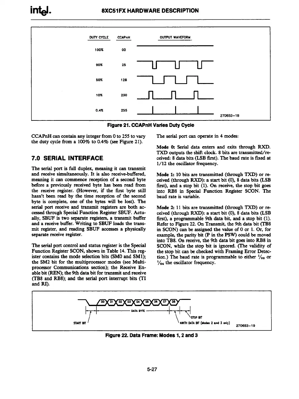
Dus-feYcLE CCAPnH OUTPUTWAVSFORM
100% 00
90%
25 ~
50%
128 ~
10Z
230 ~
0.4Z
25’ ~ ,706=-18
Figure 21. CCAPnH Variea Duty Cycle
CCAPnH oancontain any integerfrom Oto 255 to vary
the duty cycle from a 100% to 0.4% (see Figure 21).
7.0 SERIAL INTERFACE
The serial port is full duplex, meaning it ean transmit
and receivesimultaneously. It is also receive-buffered,
meaning it ean eommenee reeeption of a second byte
before a previously reeeived byte has been read fkom
the receive register. (However, if the first byte still
hasn’t beersread by the time reeeption of the seeond
byte is complete, one of the bytea will be lost). The
serial port receive and tranams“tregisters are both ac-
cessed through SpeeialFunction RegisterSBUF. Actu-
ally, SBUF is two separate registers,a transmit buffer
and a receivebuffer.Writing to SBUF loads the trans-
mit register,and reading SBUF
amxsses a physically
separatereceiveregister.
The serialport control and status registeris the Special
Function RegisterSCON, shown in Table 14.This reg-
ister contains the mode selection bits (SMOand SM1);
the SM2 bit for the multiprocessor modes (see Msdti-
ocea.sorCommunications seetion); the Receive En-pr
ablebit (REIN);the 9th data bit fortransmitand receive
(1’B8 and RB8); and the serial port interrupt bits (’H
and RI).
The serial portcan
operatein 4 modes:
Mode tk Serial data enters and exits through RXD.
TXD outputs the shift clock. 8 bits aretransrnitted/re-
cekd: 8 data bits (LSB ilrst). The baud rateis fixed at
1/12 the oscillatorfrequency.
Mode 1: 10 bits are transmitted (through TXD) or r~
ceived (throughRXD): a start bit (0), 8 &ts bita (LSB
tirst), and a stop bit (l). On reeeive, the stop bit goes
into RB8 in Special Function Register SCON. The
baud rate is variable.
Mode 2: 11 bits are transmitted (through TXD) or re-
cekd (through RXD): a start bit (0), 8 data bits (LSB
first), a programmable 9th data bit, and a stop bit (l).
Refer to Figure 22. On Transmit, the 9th data bit (TB8
in SCON) oan be assigrwdthe value of Oor L Or, for
example+the paritybit (P in the PSW) could be moved
into TBS. 0ss receiv~ the 9th data bit goeainto RB8 in
SCON, while the stop bit is ignored. (The validity of
the stop bit ean be checked with Framin
g ErrorDetec-
arnmableto either %. or
tion.) The baud rate is r.rom
Figure 22. Dsta Frame: Modes 1,2 and 3
5-27