intel.
HARDWAREDESCRIPTION OF THE 8051,8052 AND 80C51
cycleslong,and if the instructionin progressis RET2
or an accessto IE or 1P,the additionalwait time can-
not be more than 5 cycles(a maximumof one more
cycle to complete the instructionin progress, plus 4
cyclesto completethe nextinstructionifthe instruction
is MULor DIV).
Thus, in a single-interruptsystenLthe responsetime is
rdwaysmorethan 3 cyclesand lessthan 9 cycles.
SINGLE-STEPOPERATION
The 8051interrupt structure allowssingle-stepexecu-
tion with very little softwareoverhead.As previously
noted, an interrupt request will not be respondedto
whilean interrupt ofequalprioritylevelis still in prog-
ress, nor will it be respondedto after RETI until at
least one other instruction has been executed. Thus,
oncean interruptroutinehasbeenentered,it cannotbe
reentered untilat leastoneinstructionofthe interrupt-
ed programis executed.Onewayto usethis featurefor
single-stopoperationis to programoneof the external
interrupts(say,INTO)to be level-activated.The service
routinefor the interrupt willterminatewiththe follow-
ing cude:
JNB P3.2,$ ;WaitHereTill~Goes High
JB
P3.2,$ ;NowWait HereTillitGoes Low
RETI :GoBackand ExecuteOne Instruction
Nowif the ~ pin,whichisalsothe P3.2pin, is held
normallylow,the CPU willgoright into the External
Interrupt Oroutineand stay thereuntil ~ is pulsed
(fromlowto highto low).Thenit will executeRETI,
go back to the task program,executeone instruction,
and immediatelyre-enter the Extend Interrupt Orou-
tine to await the next pulsingof P3.2.One step of the
task programis executedeachtimeP3.2is puked.
RESET
Thereset input is the RSTpin, whichis the input to a
SchmittTrigger.
A reset is accomplishedby holdingthe RST pin high
for at least two machinecycles(24oscillatorperiods),
while the asciIlator h rwnning. The CPU respondsby
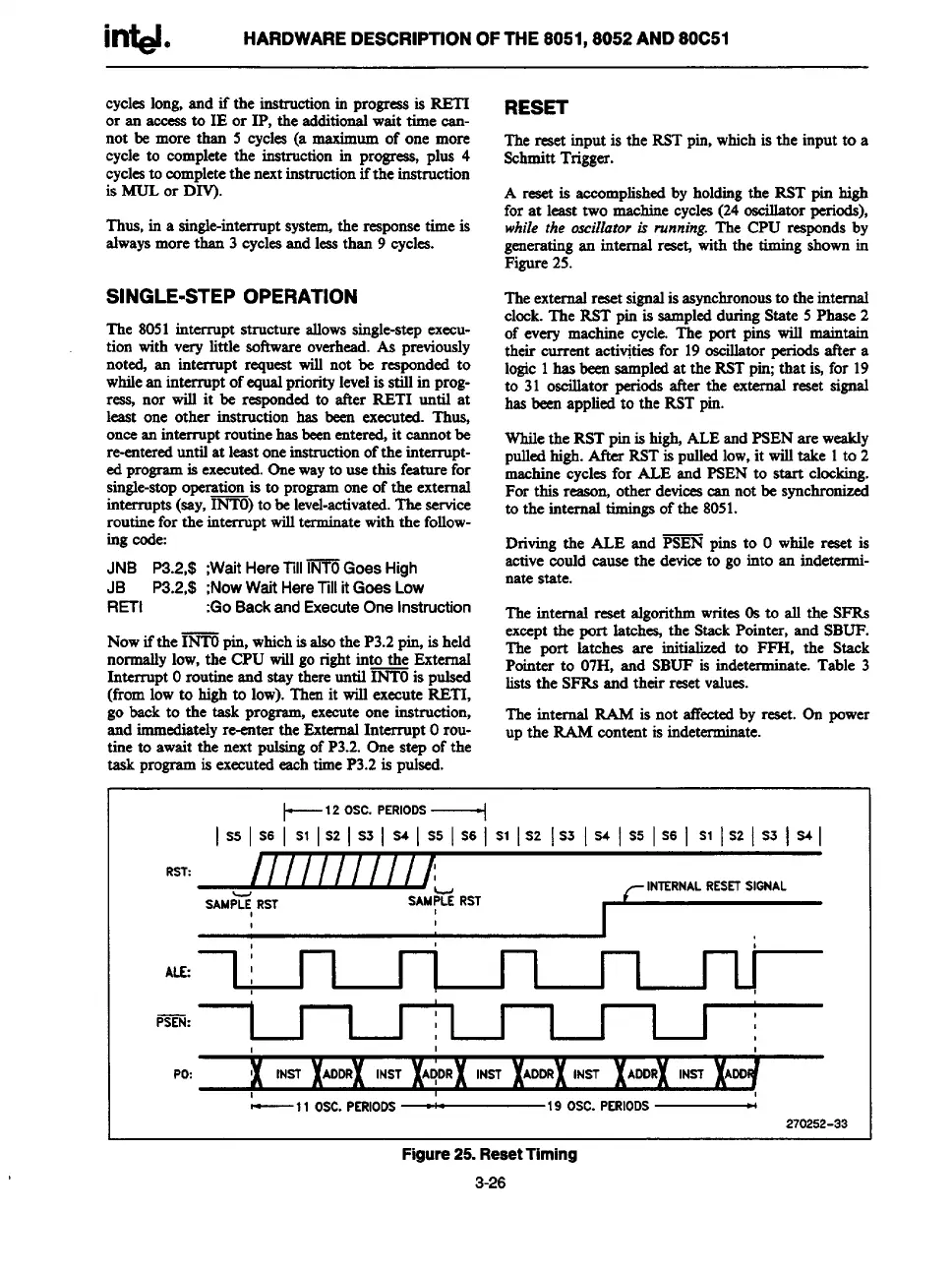
generatingan internal res@ with the timing shownin
Figure25.
Theexternalreset signalis asynchronousto the
internal
clock.The RST pin is sampledduringState 5 Phase 2
of every machine cycle. The port pins will maintain
their current activ@iesfor 19oscillatorperiodsafter a
logic1has beensampledat the RSTpin;that is,for 19
to 31 oscillator periods after the external reset signal
has beenappliedto the RST pin.
Whilethe RSTpin is high,ALEandPSENare weakly
pulledhigh.Mer RSTis pulledlow,it willtake 1to 2
machinecyclesfor ALE and PSEN to start clocking.
For this reason,other devicescan not be synchronized
to the internal timingsof the 8051.
Drivingthe ALE and PSEN pins to Owhile reset is
activecould cause the deviceto go into an indetermin-
ate state.
The internal reset algorithmwrites0s to all the SFRS
exceptthe port latch= the StackPointer, and SBUF.
The port latches are initialized to FFH, the Stack
Pointer to 07H, and SBUF is indeterminate.Table 3
lists the SFRSand their reset values.
The internal R4M is not affectedby reset. On power
up the ILkM content is indeterminate
~t2 OSC. PERIODS ~
RST:
I//l/l/l///w
IN7ERNAL RESETSIGNAL
SAMPti, RST
SAMPLE RST
,
I
~:
1
I
I ~1 I
I [
I
I
,
,
t
1
Po:
!(
INST
I ,
—11 Osc. PERIOOS
—19 OSC. PERIODS —
270252-33
Figure 25. Reset Timing
3-26