i~.
8XC51FXHARDWAREDESCRIPTION
flexibility in detiningthe Broadcast Address, but in
most applications a BroadeastAddress will be OFFH.
SADDR and SADEN are located at address A9H and
B9H, respectively. On rese~ the SADDR and SADEN
registersare initiahzed to OOHwhich defines the Given
and Broadeast Addrcaseaas XXXX XXX?(
(all don’t-
cares). This assures the C51FX serial port to be back-
wards compatibility with other MCW-51 products
which do not implement Automatic Addrmsing.
7.4 Baud Rates
The baud rate in Mcde Ois fixed:
ModeOBaudRate=
OscillatorFrequency
12
The baud rate in Mode 2 depends on the value of bit
SMOD1 in Special Function Register PCON. If
SMOD1 = O (which is the value on reset), the baud
rate is 1\e4the oscillatorfrequency.If SMOD1 = 1, the
baud rate is ~$2the oaeillatorfrequency.
Mode 2Baud Rate = 2srJoDl x ‘i’’a’o[requenq
The baud ratea in Modes 1 and 3 are deterrninedby the
Timer 1 overflow rate, or by Timer 2 overflow rak or
by both (one for transrnr“tand the other for receive).
7.5 Using Timer 1to Generate Baud
Rates
When
Timer 1 is used as the baud rate generator,the
baud rates in Modes 1 and 3 are dctermrn“ ed by the
Timer 1 overflow rate and the value of SMOD1 as fol-
lows:
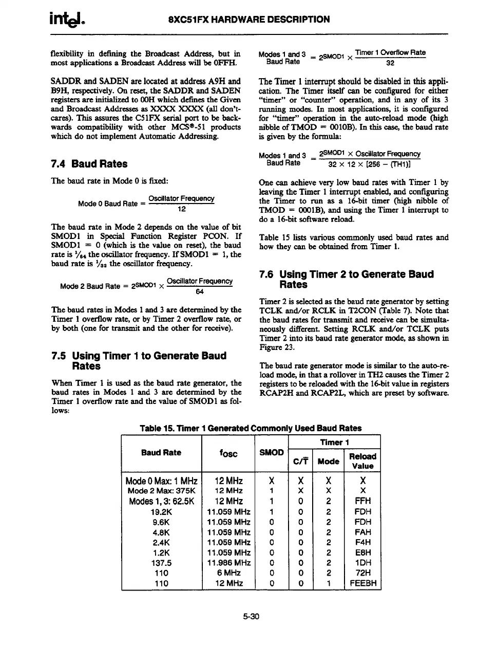
Table 15. Timel
BarsdRate
ModeOMax:1 MHz
Mode 2 Max:375K
Modes1,3:
62.5K
19.2K
9.6K
4.8K
2.4K
1.2K
137.5
110
110
Generated (
fofjc
12MHz
12 MHz
12MHz
11.059MHz
11.059 MHz
11.059MHz
11.059MHz
11.059MHz
11.986MHz
6 MHz
12MHz
MocactilR:mJ3 = 2SMOD1x
Timer1OverflowRate
32
TheTimer1interruptshouldbedisabledinthisappli-
cation.TheTimeritselfcanbe configuredfor either
“timer”or “counter”
operatiom and in any of its 3
running modes. In most applications, it is configured
for “timer” operation in the auto-reload mode (high
nibble of TMOD = OO1OB).In this casq the baud rate
is given by the formula:
Modes
I and3 = ~MOD1x OscillatorFrequency
BaudRate
32X 12 X ~56– (THl)]
Onecanaohieveverylow baud rateswithTimer1 by
leaving the Timer 1 interrupt enabled,and eontiguring
the Timer to run as a Id-bit timer (high nibble of
TMOD = OOOIB),and using the Timer 1 interrupt to
do a 16-bitsoftwarereload.
Table 15 lists various commonly used baud rates and
how they earsbe obtained from Timer 1.
7.6 UsingTimer 2 to Generate Baud
Rates
Timer 2 is selectedasthe bad rategeneratorby setting
TCLK and/or RCLK in T2CON (Table 7). Note that
the baud ratesfor transmit and receivecan be simuka-
neously different. Setting RCLK and/or TCLK puts
Timer 2 into its baud rate geueratormode, as shown in
Figure 23.
The baud rategeneratormode is similarto the auto-re-
load mode in that a rolloverin TH2 eauseathe Timer 2
registersto be reloadedwith the 16-bitvaluein registers
RCAP2H and RCAP21+ which areprsaetby software.
x
1
1
1
0
0
0
0
0
0
0
UsedSaudRates
C17
x
x
o
0
0
0
0
0
0
0
0
Timel
x
x
2
2
2
2
2
2
2
2
1
Reload
Value
x
F:H
FDH
FDH
FAH
F4H
E6H
IDH
72H
FEEBH
5-30