in~.
8XC51FXHARDWAREDESCRIPTION
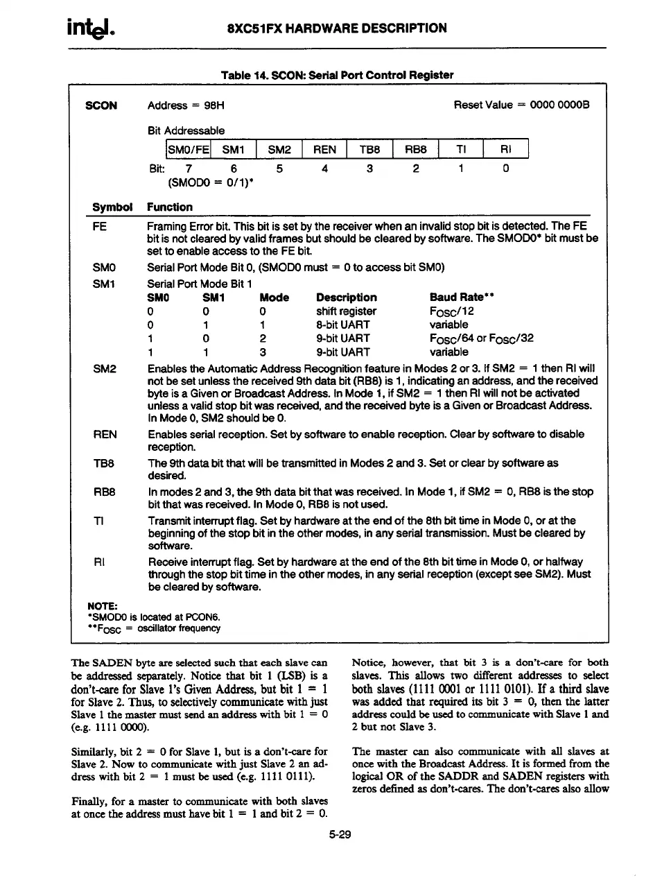
Table 14. SOON:Serial Port Control Register
SCON
Address= 98H
ResetValue= 0000OOOOB
BitAddressable
SMO/FE SM1 SM2
REN TB8
RB8 TI RI
Bit:
5
4 3 2
1 0
(SM% = 0?1)”
Svmbol Function
FE
SMO
SM1
SM2
REN
TB8
RB8
TI
RI
FramingErrorbit.Thisbitissetbythereceiverwhenaninvalidstopbitisdetected.TheFE
bitisnotclearedbyvalidframesbutshouldbeclearedbysoftware.TheSMODO*bitmustbe
setto enableaccessto the FEbit.
SerialPortModeBitO,(SMODOmust= O
to access bit SMO)
SerialPorlModeBit1
SMO
SM1 Mode
Description Saud Rate**
o 0
0
shiftregister
Foscl12
o
1 1 8-bitUART
variable
1 0 2 9-bitUART
Fosc184or Fosc/32
1 1
3
9-bitUART
variable
EnablestheAutomaticAddressRecognitionfeatureinModes2or3.IfSM2= 1thenRIwill
notbesetunlessthereceived9thdatebit(RB8)is1,indicatinganaddress,andthereceived
byteiSaGivenor BroadcastAddress.InMode1,if SM2 = 1thenRIwillnotbeactivated
unlessavalidstopbitwasreceived,andthereceivedbyteisa Givenor BroadcastAddress.
InModeO,SM2shouldbeO.
Enablesserialreception.Setbysoftwareto enablereception.Clearbysoftwareto disable
reception.
The9thdatabitthatwillbetransmittedinModes2 and3.Setorclearbysoftwareas
desired.
Inmodes2and3,the9thdatabitthatwasreceived.InMode1,if SM2= O,RB8isthestop
bitthatwas
received.InModeO,RB8is not Urjed.
Transmitinterruptflag.Setbyherdwareattheendof the8thbittimeinModeO,oratthe
beginningofthestopbitintheothermodes,inanyserialtransmission.Mustbeclearedby
software.
Receiveinterruptflag.Setbyhardwareattheendof the8thbittimeinModeO,orhalfway
throughthestopbittimeintheothermodes,inanyserialreception(exceptseeSM2).Must
beclearedbysoftware.
NOTE:
●SMOOOis Ioeated at PCON6.
●*F= = oaoillatm trequeney
The SADEN bvte areselectedsuch that each slave can
Notice,
however, that bit 3 is a don’t-care for both
be addreased-tely. Notice that bit 1 (MB) is a
slaves.This allowstwo ditTerentaddressesto seleet
don’t-careforSlave1’sGivenAddress,butbit 1 = 1
bothslaves(11110001or 11110101).If
a thirdslave
forSlave
2.l’h~ to selectivelycommunicate with just
was added that requiredits bit 3 = O,then the latter
Slave 1the mastermust sendan addreeswith bit 1 = O
addreascould be used to communicatewith Slave 1and
(e.g. 1111 0000).
2 but not Slave 3.
Similarly, bit 2 = Ofor Slave 1, but is a don’t-esre for
The master cart also communicate with all slaves at
Slave 2. Now to cammunieatewith just Slave 2 an sd-
onoe with the BroadeastAddress. It is formedfrom the
dress with bit 2 = 1 must be used (e.g. 1111 0111).
logical OR of the SADDR and SADEN registerswith
zeros defined as don’t-cares.The don’t-caresalso allow
Finally, for a master to eommunieste with both slaves
at once the addressmust havebit 1 = 1 and bit 2 = O.
5-29