intel.
83C152 HARDWAREDESCRIPTION
Note 1: Programmable in Raw transmit or receive
mode.
Afmostall the optionsavailablefromTable3.1can be
implementedwith the proper softwareto perform the
functionsthat are necessaryforthe optionsselected.In
Table3.1,ajudgmenthasbeenmadeby the authors on
which optionsare practical and which are not. What
this meansis that inTable3.1,an “N” shouldbe inter-
pretedas m
caningthat theoptioniseither not practical
whenimplementedwithuser sotlwareor that it cannot
be done.An “O” is used whenthat functionis one of
severalthat can be
implemented with the GSCwithout
additionalw software.
The GSC is targeted to operate at bit rates up to 2.4
MBps using the external clock options and up to 2
MBps usingthe internal baud rate generator,internal
data formattingand on-chipclockrecovery.The baud
rate generator allows most standard rates to be
achieved. These standards include the proposed
IEEE802.3LAN standard(1.OMBPS)and the T1stan-
dard (1.544MBPs).The baud rate is derivedfrom the
crystal frequency.This makescrystal selectionimpor-
tant whendetermining
g the frequencyand accuracy of
the baud rate.
The user needsto be awarethat after reaet,the GSCis
in C3MA/CD mode,IFS = 256bit times, and a bit
time equals8 oscillatorperiods.The GSC willremain
in this mode until the interfrarnespace expires.If the
user changesto SDLCmodeor the parametersusedin
CSMA/CD,thesechangeswillnot take effectuntil the
interfrarnespace expirea.A requirementfor the inter-
frame spacetimer to beginis that the receiverbe in an
idle state. This makesit possiblefor the GSC to te in
someothermodethan the user intendsfor a signifwant
amountof time after reset. To preventunwantedGSC
errors from occurring,the user should not enable the
GSC or the GSC interrupts for 170 machine cycles
((256 X 8)/12)after LNI bit is set.
3.2 CSMA/CD Operation
3.2.1 CSMA/CD OVERVIEW
CSMA/CD operatesby
sensingthe transmissionline
fora carrier,whichindicateslinkactivity.At the endof
linkactivity,a stationmustwaita pericdoftime,called
the deferenceperiod, before
transmission my begin.
The deferenceperiod is also knownas the interfrarne
space. The interframe space is explainedin Section
3.2.3.
Withthistypeofoperation,thereis alwaysthe possibil-
ity of a collisionoccurringafter the deferenw period
due to line delays.If a collisionis detectedafter trans-
missionis started, a jammingmechanismis used to en-
sure that all stations monitoringthe line are aware of
the collision.A resolutionalgorithmis thenexecuted
to
resolvethe contention.Thereare three differentmodea
ofcollisionresolutionmadeavailableto the useron the
C152.Re-transrnissionis attemptedwhena resolution
algorithmindicatesthat a station’soppommityhas ar-
rived.
Normally,in CSMA/CD, re-tranamissionslot assign-
mentsare intendedto be random.Thismethodgivesall
stationsan equal opportunityto utilizethe serial com-
municationlinkbut alsoleavesthe possibilityof anoth-
er collisiondue to two stations having the same slot
assignment.There is an optionon the C152whichal-
lowsall the stationsto havetheir slotassignmentspre-
viouslydetemrm“ .4 by user software.This pre-asaign-
ment of slots is called the deterministic resolution
mode.This methodallowsresolutionafter the first col-
lisionand ensureathe acceasofthe linkto each station
during the resolution.Deterministicresolutioncan be
advantageouswhenthe link is beingheavilyused and
collisionsare frequentlyoccurringand in real time ap-
plicationswheredeterminismisrequired.Deterministic
resolutionmay also be desirableif it is knownbefore-
handthat a certain station’scommunicationneedsto be
prioritizedover those of other stationsif it is involved
in a collision.
3.2.2
CSMAICD FRAME FORMAT
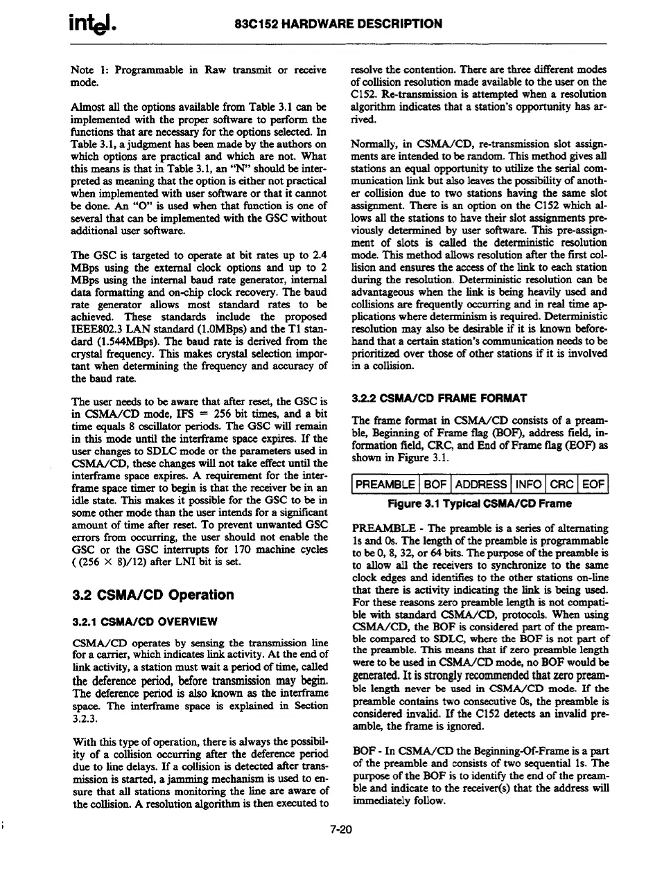
The frameformat in CSMA/CD consistsof a preamb-
le, Beginningof Frame tlag (BOF),address field, in-
formationfield,CRCjandEndofFrame flag(EOF) as
shownin Figure 3.1.
PREAMBLE BOF ADDRESS INFO CRC EOF
Figure
3.1Typical CSMA/CD Frame
PREAMBLE- The preambleis a seriesof alternating
1sand 0s. The lengthofthe preambleis programmable
tobeO,8,32,or 64bits.Thepurposeofthe preambleis
to allow all the receiversto synchronizeto the same
clockedges and identifiesto the other stations on-line
that there is activityindicatingthe link is beingused.
For these reasonszero preamblelengthis not compati-
ble with standard CSMA/CD, protocols.When using
CSMA/CD, the BOF is consideredpart of the pream-
ble comparedto SDLC,wherethe BOF is not part of
the preamble.This meansthat if zero preamblelength
wereto be usedin CSMA/CDmcde,no BOFwouldbe
generated.It isstronglyrecommendedthat zeropreamb-
le length never be used in CSMA/CD mode. If the
ble is
preamblecontains two consecutive0s, the pream
consideredinvalid.If tie C152detects an invalidpre-
amble the frame is ignored.
BOF-In CSMA/CD the Begirming-Of-Frarneisa part
ofthe preambleand consistsof two sequential1s.The
PUPOXof the BOFis to identifytheend of the preamb-
le and indicate to the receiver(s)that the address will
immediatelyfollow.
I
7-20