i~e
83C152HARDWARE DESCRIPTION
The
resultis thatin this @c* css c~el o hss
FunctionRegister(SFR).If DAS = 1and IDA = 1,
to waituntil channel1completesits BurstmodeDMA,
the destinationis in Internal Data WM.
and then hasto wait for an Instructioncycleto begen-
erated,beforeit cartcontinueits ownDMAto TFIFO.
IDA (IncrementDestinationAddress)If IDA = 1,the
The delayin servicingTFIFO can causean Underflow
destinationaddressis automaticallyincrementedafter
conditionin the GSC transmission.
each bytetransfer. If IDA = O,it is not.
The delay will not occur if channel 1 is configuredto
SASspeeitlesthe SourceAddressSpace.If SAS = 0,
Alternate Cyclesma sincechannelOwouldthen see
the sourceis in External Data Memory.If SAS = 1
the Instructioncyclesit needsto completeits logicre-
and ISA = O,the sourceis an SFR. If SAS = 1 and
quirementsfor amertingits request.
ISA = 1,the sourceis internal Data RAM.
4.4.1 DMA Arbitration with Hold/Hold Ack
ISA (Increment source Address) If ISA = 1, the
sourceaddressis automaticallyincrementedafter each
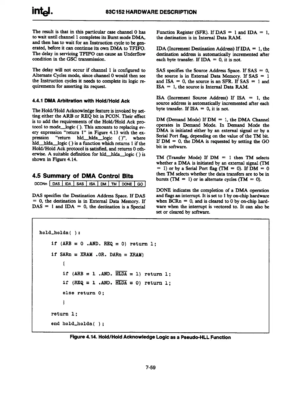
TheHold/Hold Acknowledgefeatureis invokedby set-
bytetransfer. If ISA = O,it is not.
ting eitherthe ARBor REQ bit in PCON.Theireffect
is to add the requirementsof the Hold/Hold Ack pro-
DM (D
emandMode)If DM = 1,the DMA Channel
tocolto mode-logic (). This amountsto replacingev-
opcrates in
Demand Mode. In Demand Mcde the
ery expression“return 1“ in Figure 4.13 with the ex-
DMA is initiated either by an external signal or by a
pression “return hld-hlda-logic ( )“, where
SerialPort tlag, dependingon the valueof the TM bit.
hld-idda-logic ( ) is a fimctionwhichreturns 1if the
If DM = O,the DMA is requestedby settingthe GO
Hold/Hold Ackmotocolis satisfied,andreturnsOoth-
bit in software.
erwise.A suitabfi definitionfor hltida-logic ( ) is
shownin Figure4.14.
TM (Transf~ Mode) If DM = 1 then TM selects
whethera DMA is initiatedby an
external signal (TM
= 1)
or by a SerialPort flag (TM = O).If DM = O
4.5Summaryof DMA ControlBita
then TM selectswhethertie data transfersare to be in
bursts (TM = 1)or in alternate cycles(TM = O).
DCONn [ DAS / IDA I SAS I ISA I DMI TMI DONEI GOI
DONE indicatesthe completionof a DMA operation
DASspccitlesthe Destination AddressSpace.If DAS
andtlagsan interrupt.It is setto 1byon-chiphardware
= O,the destinationis in External Data Memory.If
whenBCRn = O,and is clearedto Oby on-chiphard-
DAS = 1 and IDA = O,the destinationis a Special
ware whenthe interrupt is vectoredto. It can also be
setor clearedby software.
hold-holda( ) :
if (ARB
= O .AND. REQ= O) return 1;
if sARn =
XRAM. OR. DARn= XRAM)
{
if (ARB =
1 .AND. ~ = 1) return 1 ;
if (REQ =
1 .AND. HLDA=
O) return 1;
else return
O ;
)
return 1 ;
end hold-holda ( ) ;
Figure 4.14. Hold/Hold Acknowledge Logic as a Paeudo-HLL Function
7-59