EasyManua.ls Logo

Intel MCS 51 User Manual

Intel MCS 51
334 pages
To Next Page IconTo Next Page
To Previous Page IconTo Previous Page
Page #50 background imageLoading...
Page #50 background image
i~.
MCS@-51PROGRAMMER’SGUIDE AND INSTRUCTION SET
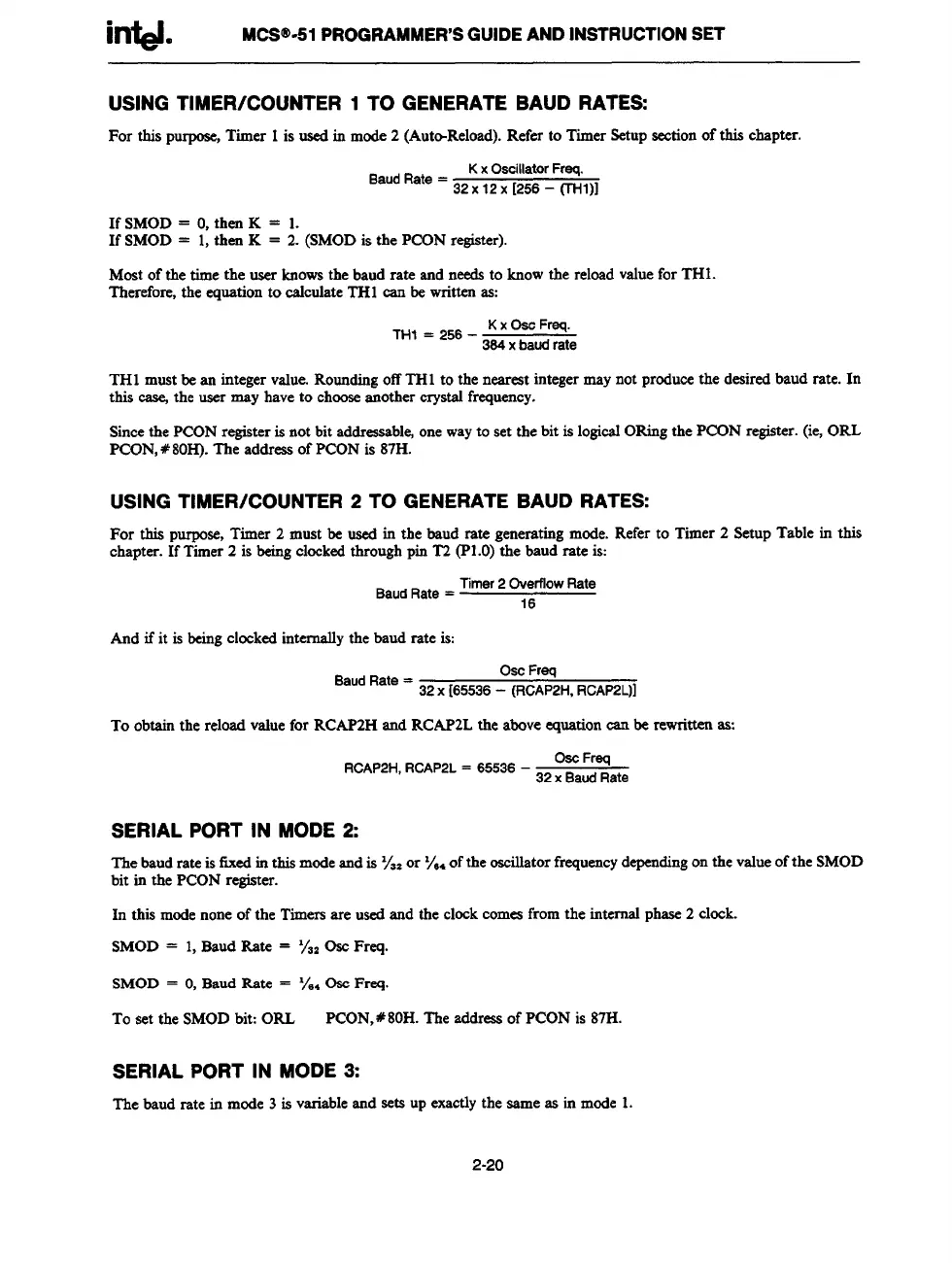
USING TIMER/COUNTER 1 TO GENERATE BAUD RATES:
For this purpose,Timer 1is usedin mode2 (Aut@Reload).Refer to TimerSetupsectionof this chapter.
BaudRate=
KxOscillatorFreq.
32X12x [256 (THI)]
If SMOD = O,then K = 1.
If SMOD = 1,then K = 2. (SMODis the PCONregister).
Most of the time the user knowsthe baud rate and needsto knowthe reloadvaluefor TH1.
Therefore,the equationto calculateIT-Hcan be writtenas:
TH1 mustbean integer value.RoundingoffTHl to the neareatintegermaynot producethe desiredbaud rate. In
this casejthe user may haveto chooseenother crystal frequency.
Sincethe PCONregisteris not bit addressable,onewayto set the bit is logicalORingthe PCON register.(ie,ORL
PCON,#80H). The addressof PCONis 87H.
USING TIMER/COUNTER 2 TO GENERATE BAUD RATES:
For this purpose,Timer 2 must be used in the baud rate generatingmode.Refer to Timer 2 SetupTable in this
chapter. If Timer2 is beingclockedthroughpin T2 (P1.0)the baud rate is:
BaudRate= Timer2Overflow
Rate
16
And if it is beingclockedinternallythe baud rate is:
BaudRate=
OscFraq
32X [65536- (RCAP2H,RCAP2L)]
To obtainthe reloadvaluefor RCAP2Hand RCAP2Lthe aboveequationcan be rewrittenas:
RCAP2H,RCAP2L= 65536 32;:a::ate
SERIAL PORT IN MODE 2:
The
baudrate is fixedin thismodeandis 7,, or%. ofthe oscillatorfrequencydpding on the v~ue ofthe SMOD
bit in the PCONregister.
In this modenoneof the Timersare usedand the clockcomesfromthe internalphase2 clock.
SMOD = 1,BaudRate = YWOsc Frcq.
SMOD = O,Baud Rate = yWw FrMI.
To set the SMODbit: ORL
pcON, #80H. The addressof PCONis 87H.
I
SERIAL PORT IN MODE 3:
The
baud rate in mode3 is variableand sets up exactlythe same as in mode 1.
2-20

Table of Contents

Question and Answer IconNeed help?

Do you have a question about the Intel MCS 51 and is the answer not in the manual?

Intel MCS 51 Specifications

General IconGeneral
Architecture8-bit
Number of Instructions111
Clock Speed12 MHz
Register Size8-bit
Internal RAM128 bytes
Internal ROM4 KB
External Memory64 KB
I/O Pins32
Timers2
Serial Port1
Interrupts5
Operating Voltage5V
UARTYes
Program Memory4 KB
RAM128 bytes
Instruction SetCISC

Summary

MCS® 51 Family of Microcontrollers Architectural Overview

THE MCS®-51 INSTRUCTION SET

Provides an overview of the MCS®-51 instruction set, optimized for 8-bit control applications.

Interrupt Structure

Overview of the 8051 interrupt structure, sources, and vectoring.

MCS® 51 Programmer’s Guide and Instruction Set

MCS®-51 INSTRUCTION SET

Provides a summary of the 8051 instruction set, including mnemonics and operands.

8051, 8052 and 80C51 Hardware Description

TIMER/COUNTERS

Describes Timer 0 and Timer 1, including operating modes and control registers.

8XC52/54/58 Hardware Description

8XC51FX Hardware Description

PORT STRUCTURES AND OPERATION

Details port structures, I/O configurations, and external memory access.

SERIAL INTERFACE

Covers serial port modes, framing error detection, and baud rate generation.

87C51GB Hardware Description

SPECIAL FUNCTION REGISTERS

Provides a map of the SFR space and their reset values.

SERIAL PORT

Details the serial port's modes, framing error detection, and baud rates.

INTERRUPTS

Covers interrupt sources, enable registers, and priority levels.

83C152 HARDWARE DESCRIPTION

Related product manuals