int&
HARDWARE DESCRIPTION OF THE 8051,8052 AND 80C51
more:Timer 2. AUthree can be ccmflgurecito operate
eitheras timers or eventcounters.
In the “Timer” function,the register is incremented
everymachinecycle.Thw onecanthinkofit ascount-
ingmachinecycles.Sincea machinecycleconsistsof 12
oscillatorperiods,the countrate is 1/,, of the oscillator
frequency.
In the “Counter” timction,the register is incremented
in responseto a l-to-Otransition at its corresponding
externrdinput pin, TO,T1 or (in the 8052)T2. In this
timction,the
externalinputis sampledduringS5P2of
everymachinecycle.Whenthe samplesshowa highin
onecycleand a lowinthe nextcycle,the countisincre-
mented.The new count value appeara in the register
duringS3P1of the cyclefollowingthe onein whichthe
transitionwasdetected.Sinceit takes 2 machinecycles
(24oscillator periods)to recognizea l-to-Otransition,
the
maxiMuMcount rate is 2/24of the oaciliator fre-
quency.There are no restrictionson the duty cycle of
the external input signaf,but to ensure that a given
level is sampled at least once before it changes, it
shouldbe held for at least onefull machinecycle.
In addition to the “Timer” or “Counter” selection,
TimerOand Timer 1 have four operatingmodesfrom
whichto select.Timer 2, in the 8052,has three modes
of operation: “Capture,
“ “Auto-Relrxid”and “baud
rate generator.”
TimerOandTimer1
TheaeTimer/Counteraarepreaent inboththe 8051and
the 8052.The “Timerr’or “Counter”functionis aelect-
edbycontrolbits Cfl in the SpeciaiFunctionRegister
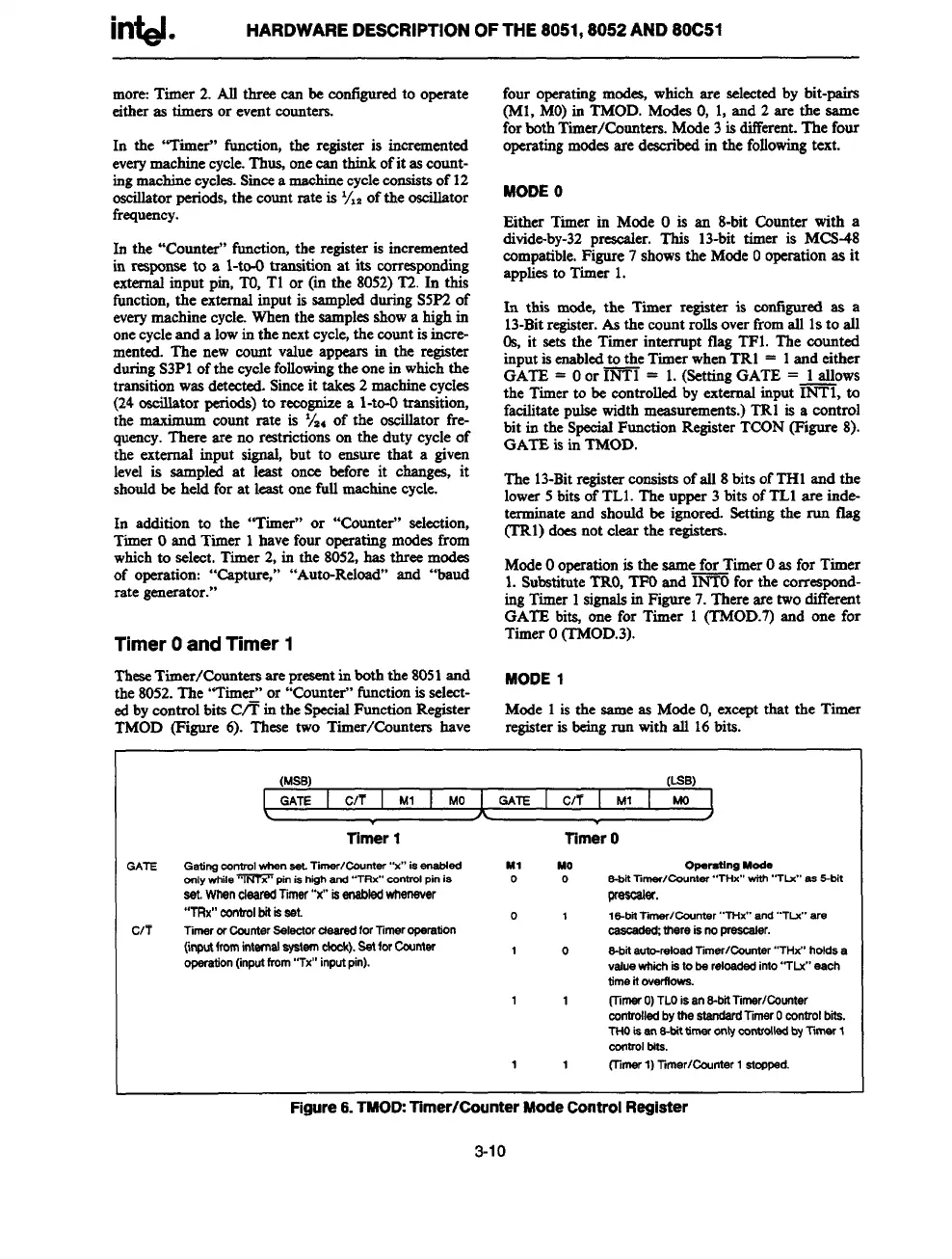
TMOD (Figure 6). These two Timer/Countem have
four operatingmod- which are selectedby bit-pairs
(M1.MO)in TMOD. ModesO,1, and 2 are the same
forbothTimer/Counters.Mode3isdifferent.The four
operatingmodesare describeditsthe followingtext.
MODEO
EitherTimerin ModeO is an 8-bit Counter with a
divide-by-32preacaler. This 13-bit timer is MCS-48
compatible.Figure7 showsthe ModeOoperationas it
appliesto Timer 1.
In this mode, the Timer regiater is configuredas a
13-Bitregister.As the countrollsoverfromail 1sto ail
0s, it sets the Timer interrupt flag TF1. The cmnted
inputisenabledto the TimerwhenTR1 = 1and either
GATE = Oor ~ = 1.(SettingGATE = 1aflows
the Timerto be controlledby externafinput INT1, to
facilitatepulsewidthmeasurements.)TRl is a control
bit in the SpeciafFunctionRegisterTCON(Figure 8).
GATE is in TMOD.
The 13-Bitregisterconsistsofail 8bitsofTHl and the
lower5 bits ofTL1.The upper 3 bits ofTLl are ittde-
terminateand shouIdbe ignored.Settingthe run flag
(’TR1)doesnot clear the registers.
ModeOoperationis the samefor TimerOas for Timer
1.SubstituteTRO,TFOand ~ for the correspond-
ingTimer 1sigmdsin Figure7.Thereare twodif%rent
GATE bia one for Timer 1 (TMOD.7)and one for
TimerO(TMOD.3).
MODE 1
Mode
1is the sameas ModeO,exceptthat the Tima
registeris beingrun with all 16bits.-
(MSB)
(LSB)
GATE C/T I Ml I MO I GATE C/7 I Ml
MO
A
Timer 1 Timer O
Gadngconrrol
whensaLTirnar/Countar “x” isanablad
WI
MO
Opamtfng Mode
cmlywhilempin ishiohand “TRx’”mntrol pinis
o 0
S-bitlimar/@ntar’’THX” with.<TIJ,,as ~it
set
WhencberedTimaf “x” isanabledwharfaver
prese%r.
“7Rx”
eontrolbitkeat.
o 1
IS-bil T!mar/Ccunter 4“THx’,and 4.TIX am
Timaror CounterSalaetor daaradfor Timer opwstiOn
cascadad;there is no ~r.
(inwtfromifttmelwetafn ebek). sattorcountar
Won (inputfrom“Tx” inputpin).
1
0
S-bitauto-reloadTimSr/~ntar “THx” holdsa
valuewhichistoba reloadadinfo“TLx” asch
time it OYWIIOWS.
1
1 (i_knwO)TLOisanS-bitTimer/Counter
mntrolled bythe
st@ard TimarOcontrolbti.
THOisanB-bitWwr@rmntdldbytimarI
CentmlMs.
1
1
flimerl) 7imer/Ccunter 1 stcopad.
Figure 6.TMOD: Timer/Counter Mode Control Register
3-1o