in~.
M~@-51 ARCHITECTURAL OVERVIEW
CTIAC]
FOIRSIIRBO[ OVI
I
P
I
b a a
A
*
A
CARRYFLAGRECEIVESCMi/fmw;
1
KWO
PARllYOFACCLWUIATORSS7
FROU BIT 1 Of ALU OPERANOS
~ NARoWARCTO 1 IF IT CONTAINS
AN 000 NUMBEROF 1S, OTHERWISE
171SRESE7TO0
Psw6—
— Psw 1
AUXILIARYCARRYFLAG RECEIVES
CARRYOUT FROM B171 OF
USER OEFINABLEFUG
AOOMON OPERANOS
nw5
Psw 2
GENERALPURPOSES7ATUS FLAG
OVERFLOWFIAO SET BY
ARITIMCWOPERAl!ONS
REGtS7ERBANKSW’% t
Psw3
REOSJERBANKSELECTBll O
270251-10
-. .- . . . . . .- . . . . . . .. . . . ------ ----
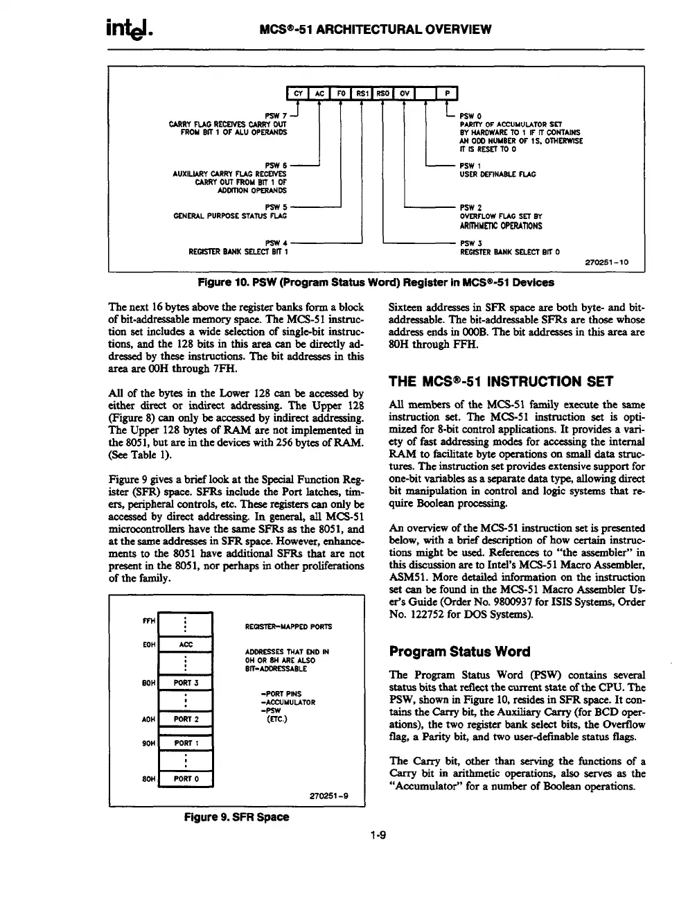
Figure 1u. Psw (Progrsm ssssus worn) Register m mc5w-51 t2evtces
The next 16bytea above the register bankBform a block
!%teers addresses in SFR mace are both byte. and bit.
of bit-addressable memory apace. The MCS-51 instruc-
tion set includes a wide seleetion of single-blt instruc-
tions, and the 128 bits in this area can be directly ad-
dressed by these irsstmctions. The bit addreascs in this
area are W)Hthrough 7FH.
All of the bytes in the LQwer 128 can be accessed by
either direct or indirect addressing. The Upper 128
(Figure 8) can only be accessed by indirect addressing.
The Upper 128 bytes of RAM are not implemented in
the 8051,but me in the devices with 256bytea of RAM.
(Se Table 1).
Figure 9 gives a brief look at the Special Funotion Reg-
ister (SFR) space. SFRS include the Port latchea, tim-
ers, pe2iphA controls, etc. l%ese registers can only&
-seal by dmect addressing. In general, all MCS-51
microcontrollers have the same SFRB as the 8051, and
at the same addresses in SFR space. However, enhance-
ments to the 8051 have additional SFRB that are not
present in the 8051, nor perhaps in other proliferations
of the family.
“u
RE~MAPPSO POR7S
EOH
m
AOORESSES7NAT END IN
OH OR EN ARCALSO
B~-AOORESSABLE
80H
B
PORT.3
AOH
Porn 2
90H
POR7 1
J-A--I
-POR7 PINS
-ACCUMULATOR
-Psw
(E7c.)
270251-9
addressable. The blt-addre&able SFRS are ‘those whose
address ends in 000B. The bit addresses in this ares are
80H
throUgh FFH.
THE MCS@-51 INSTRUCTION SET
All
members of the MCS-51 family execute the same
instruction set. The MCS-51 instruction set is opti-
mized for 8-bit control applications. It provides a vari-
ety of fast addressing modes for accessing the internal
MM to facilitate byte operations on small data struc-
tures. The instruction sd provides extensive support for
one-bit variables as a separate data t% allowing direct
blt manipulation in control and logic systems that re-
quire Boolean prmessirsg.
An overview of the MCS-51 instruction set is prrsented
below, with a brief description of how certain instruc-
tions might be used. References to “the assembler” in
this discussion are to Intel’sMCS-51 Macro Assembler,
ASM51. More detailed information on the instruction
set can be found in the MCS-51 Macro Assembler Us-
er’s Guide (Grder No. 9W3937 for 1S1SSystems, Grder
No. 122752 for DOS Systems).
Program Status Word
The Program Status Word (PSW) contains several
status bits that reflect the current state of the CPU. The
PSW, shown in Figure 10,resides in SFR space. It con-
tains the Csrry bi~ the Auxdiary Carry (for BCD oper-
ations), the two register bank select bits, the Gvesflow
flag, a Parity bit, and two userdefinable status tlags.
The Carry bit, other than serving the functions of a
Carry bit in arithmetic operations, also sesws as the
“Accumulator” for a number of Boolean operations.
Figure 9. SFR Spsce
1-9