i~.
8XC51FXHARDWAREDESCRIPTION
while the RST pin is high, the port pins, ALE and
PSEN areweakly pulled high. After RST is pulled low,
it will take 1to 2 machine cycles for ALE and FSEN to
startclocking. For this reason, other devices can not be
synchronizedto the internal timings of the 8XC51FX.
Driving the ALE and PSEN pins to O while react is
active could cause the device to go into an indetermi-
nate state.
The internalreset algorithm redefinesall the SFRS. Ta-
ble 1 lists the SFRS and their resetvalues. The internal
RAM is not affected by reset. On power up the RAM
content is indeterminate.
9.1 Power-On Reset
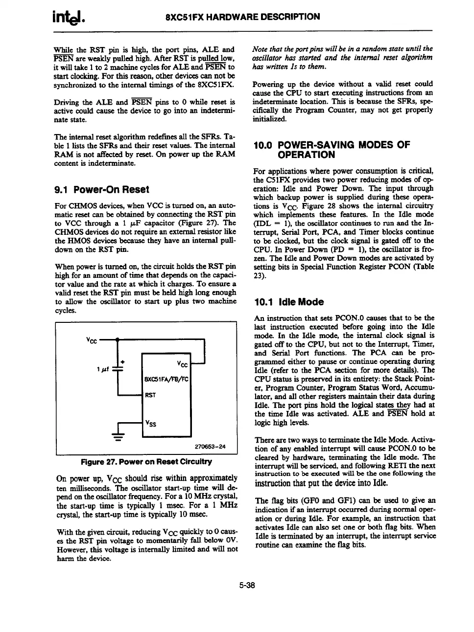
For CHMOSdevices, when VCC is turned on, an auto-
matic resetcan be obtained by connecting the RST pin
to VCC through a 1 pF capacitor (Figure 27). The
CHMOSdevices do not requirean externalreaistorlike
the HMOS devices because they have an internal pull-
down on the RST pin.
When poweris turned on, the circuit holds the RST pin
high for an amount of time that depends on the eapaei-
tor value and the rate at which it charges.To ensure a
valid resetthe RST pin must be held high long enough
to allow the oscillator to start up plus two machine
cycles.
1 pf
n’
1
+
v#J
3XC51FA/lB/FC
RST
%s
=
270S53-24
Figure 27. Power on Reset Circuitry
Onpowerup, VCCshouldrisewithinapproximately
ten
millkeonds. The oscillator start-uDtime will de-
pend
on the oscillator frequency.For a iOMHz crystal,
the start-up time is
typically1 msec.For a 1 MHz
crystal,the
start-uptime istypically10 masc.
With the given circuit, reducingVcc quickly to Ocaus-
es the RST pin voltage to momentarily fall below OV.
However,this voltage is internally limited and will not
harm the device.
Note that theportpins wiilbe in a mndom state until the
oscillator has started and the internal reset aigorithm
has wn”ttenIs to them.
Powering up the device without a valid reset could
cause the CPU to start executing instructions from an
indeterminatelocation. This is because the SFRS, spe-
cifically the Program Counter, may not get properly
initialized.
10.0 POWER-SAVING MODES OF
OPERATION
For applicationswhere power consumption is critical,
the C51FX provides two power reducing modes of op-
eration: Idle and Power Down. The input through
which backup power is supplied during these opera-
tions is Vcc. Figure 28 shows the internal circuitty
which implements these featurea. In the Idle mode
(IDL = 1), the oscillator continues to run and the In-
terrupt, Serial Port, PCA, and Timer blocks continue
to be clocked, but the clock signal is gated off to the
CPU. In Power Down (PD = 1), the oscillatoris fro-
zen. The Idle and Power Down modes areactivatedby
setting bits in Special Function Register PCON (Table
23).
10.1 Idle Mode
An
instructionthat sets PCON.Ocauses that to be the
last instruction executed before going into the Idle
mode. In the Idle mode, the internal clock signal is
gated off to the CPU, but not to the Interrupt,Timer,
and Serial Port fimctions. The PCA can be pro-
grammed either to pause or continue operatingduring
Idle (referto the PCA section for more details). The
CPU status is preservedin its entirety:the Stack Point-
er, ProgramCounter, ProgramStatus Word, Accumu-
lator, and all other registersmaintain their data during
Idle. The port pins hold the logical states they had at
the time Idle was activated. ALE and FSEN hold
at
logic high levels.
There are two ways to terminate the
Idle Mode. Activa-
tion of any enabledinterrupt will cause PCON.Oto be
cleared by hardware,terroinatingthe Idle mode. The
interruptwill be serviced, and following RETI the next
instruction to be executed will be the one fOUowingthe
instructionthatputthedeviceintoIdle.
The flag bits (GFO and GF1) can be used to give art
indication if an interrupt occurredduring normal oper-
ation or during Idle. For
example an instruction that
activates Idle can also set one or keth flag bits. Wheo
Idle is terminated by an interrupt, the interruptservice
routine can examin
e the flag bits.
5-38