i~.
83C152 HARDWARE DESCRIPTION
CRCE+
1 set
EOF
‘RDN
RECEIVEO
270427-50
1
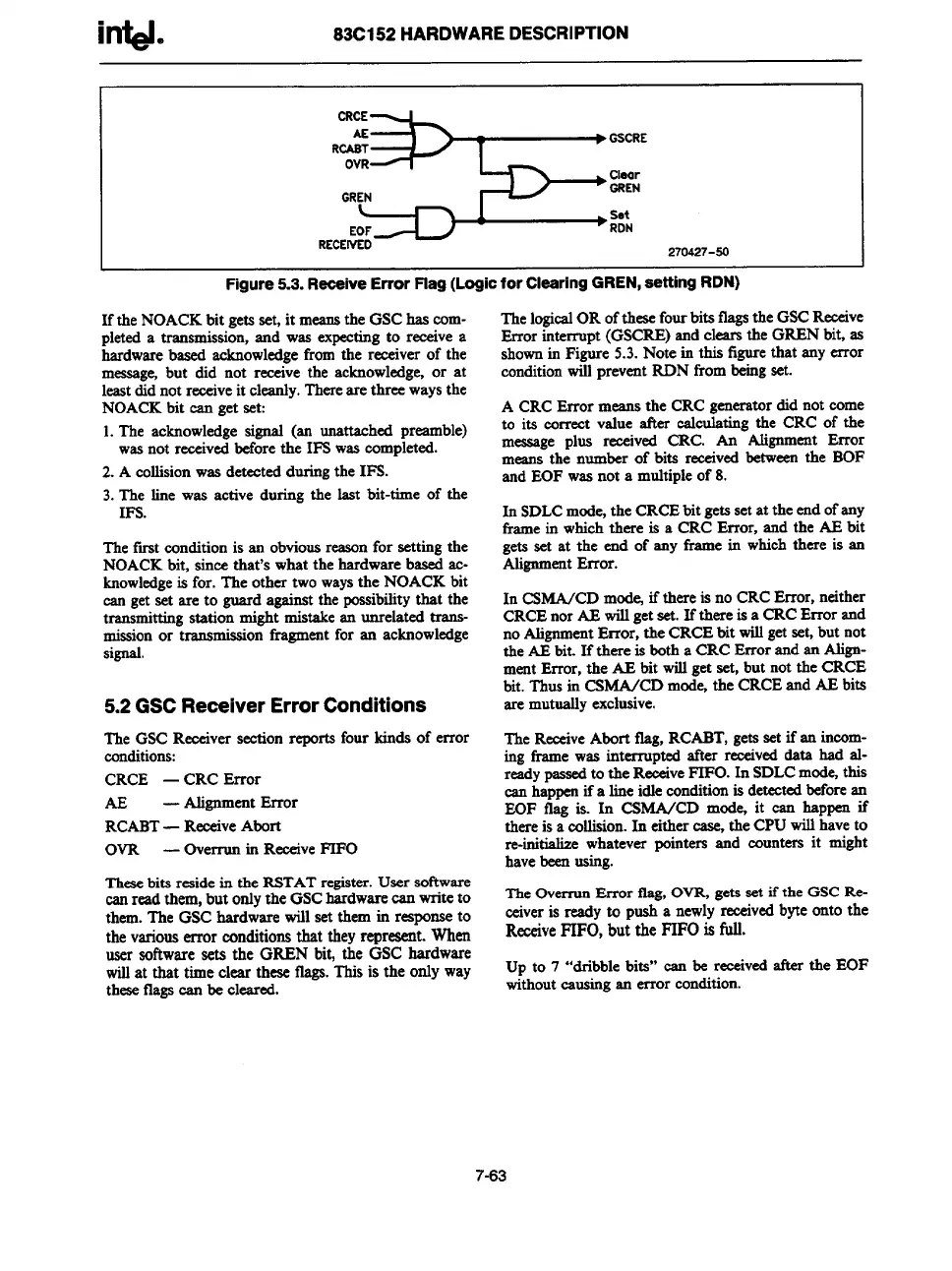
Figure 5.3. Reeeive Error Flag (Logic for Clearing GREN, setting RDN)
If the NOACKbit getsset, it meansthe GSChas com-
pleted a transmission,and was expectingto receivea
hardwarebased acknowledgefrom the receiver of the
message,but did not receive the acknowledge,or at
leastdidnot receiveit cleanly.Thereare three waysthe
NOACKbit can get set:
1.The acknowledgesignal (an unattached preamble)
wasnot receivedbeforethe IFS wascompleted.
2. A collisionwas detectedduringthe IFS.
3.The line was active during the last bit-time of the
IFS.
Thefirst conditionis an obviousreasonfor settingthe
NOACKbit, since that’s what the hardware based ac-
knowledgeis for. The other two waysthe NOACK bit
~ get set are to guard against the possibilitythat the
transmittingstation might mistakean unrelated trans-
missionor transmissionfmgmentfor an acknowledge
signal.
5.2 GSC ReceiverErrorConditions
The GSCReeeiversection reports four kinds of error
conditions:
CRCE — CRC Emor
AE
— AlignmentError
RCABT—ReceiveAbort
OVR
—
Overrunin ReceiveFIFO
These
bits reaide in the RSTATregister.User software
canread them,but onlythe GSChardwarew writeto
them.The GSC hardware will set them in responseto
the variouserror conditionsthat theyrepresent. When
user softwaresets the GREN bit, the GSC hardware
willat that time clear these flags.This is the only way
theseflagscan be cleared.
The logicalOR ofthesefourbits flagsthe GSCReceive
Error interrupt (GSCRE)and clearsthe GREN bit, as
shownin Fimre 5.3.Note in this figurethat any error
conditionW preventRDN from=g set.
A CRCError means the CRC generatordid not come
to its correct value after calculatingthe CRC of the
message plus roxived CRC. An Alignment Error
means the number of bits receivedbetweenthe BOF
and EOF wasnot a multipleof 8.
In SDLCmode,the CRCEbit getsset at the endofany
framein whichthere is a CRC Error, and the AE bit
gets set at the end of any frame in whichthere is an
AlignmentError.
In CSMA/CDmodejif there is no CRCError, neither
CRCEnor AE willget set. If there is a CRCError and
noAlignmentError, the CRCEbit willgetset,but not
the AEbit. If there is botha CRC Error and an Align-
mentError, the AE bit willget set, but not the CRCE
bit. Thusin CSMA/CD mode,the CRCEand AE bits
are mutuallyexclusive.
TheReceiveAbort ilag, RCABT,getsset if an incom-
ing frame was interrupted after receiveddata had al-
readypassedto the ReceiveFIFO. In SDLCmode,this
canhappenifa line idleconditionis detectedbeforean
EOF flag is. In CSMA/CD mod%it can happen if
thereis a collision.In either case,the CPUwillhaveto
re-initializewhatever pointers and counters it might
havebeenusing.
TheOverrunError flag,OVR,gets set if the GSCRe-
ceiveris ready to push a newlyreceivedbyteonto the
ReceiveFIFO, but the
FIFOisfull.
Up to 7 “dribble bits” can be receivedafter the EOF
withoutcausingan error condition.
7-63