i@.
HARDWARE DESCRIPTION OFTHE 8051,8052 AND 80C51
Frequency,toleranceand temperaturerangeare deter-
minedby the systemrequirements.
A morein-depthdiscussionofcrystalspeciticstions,ce-
ramicreaonstors,and the selectionofvaluesfor Cl and
C2can be foundin ApplicationNoteAP-155,“Oscilla-
tors for Microcontrollers,”which is included in the
Embedded Appticatwnz Handbook.
To drive the HMOS parts with an external clock
source,applythe externalclocksignalto XTAL2,rmd
groundXTAL1,as shownin Figure32.A pullupreais-
tor may be used (to increasenoisemargin),but is op-
tionalifVOH ofthe drivinggateexceedsthe VIH MIN
specificationof XTAL2. --
+-!4
msl
EXTSRNAL
oeenLAloR
XTAU
SIGNAL
t
XTAL1
GATE
V&
v=
mTsu.PoLe
OUTPUT ‘
270252-25
Figure32.DrivingtheHMOSMCS@-51
PartewithanExtemsdClockSource
CHMOSVersions
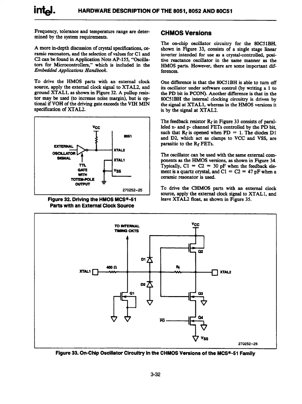
The on-chip oscillator circuitry for the 80C51BH,
shownin Figure 33,
consists of a singlestage linear
inverterintended for use as a crystal-controlled,posi-
tive reactance oscillator in the same manner as the
HMOSparta. However,there are someimportant dif-
ferences.
Onedifferenceis that the 80C51BHis able to turn off
its oscillatorunder softwarecontrol (by writinga 1to
the PD bit in PCON). Anotherdifferenceis that inthe
80C51BHthe internal clockingcircuitry is driven by
the signalat XTAL1,whereasin the HMOSversionsit
is by the signalat XTAL2.
Thefeedbackresistor Rfin Figure33consistsof paral-
leledn- and p- channel FETs controlledbythe PD bit,
suchthat Rf is openedwhenPD = 1.The diodeaD1
and D2, which act as clamps to VCC and VSS,are
parasiticto the Rf FETs.
Theoscillatorcan be usedwiththe sameexternalcom-
ponentsas the HMOSversio~ as shownin Figure 34.
Typically,Cl = C2 = 30pF whenthe feedbackele-
mentisa quartz crystal, and Cl = C2 = 47pF whena
ceramicreaonatoris used.
To drive the CHMOS parts with ass external clock
sourcq applythe externalclocksignalto XTAL1,and
leaveXT-=2 float, as shownin F&ssre35.
xrALl
m
L
Mon
c1
02
s
r?“
al
I
Q%e
270252-26
Figure 33. On-Chip Osoillsstor Circuitry In the CHMOS Versions of the MCS@-51 Family
3-32