i~.
MCS@-51 ARCHITECTURAL OVERVIEW
Jump lnstruMlons
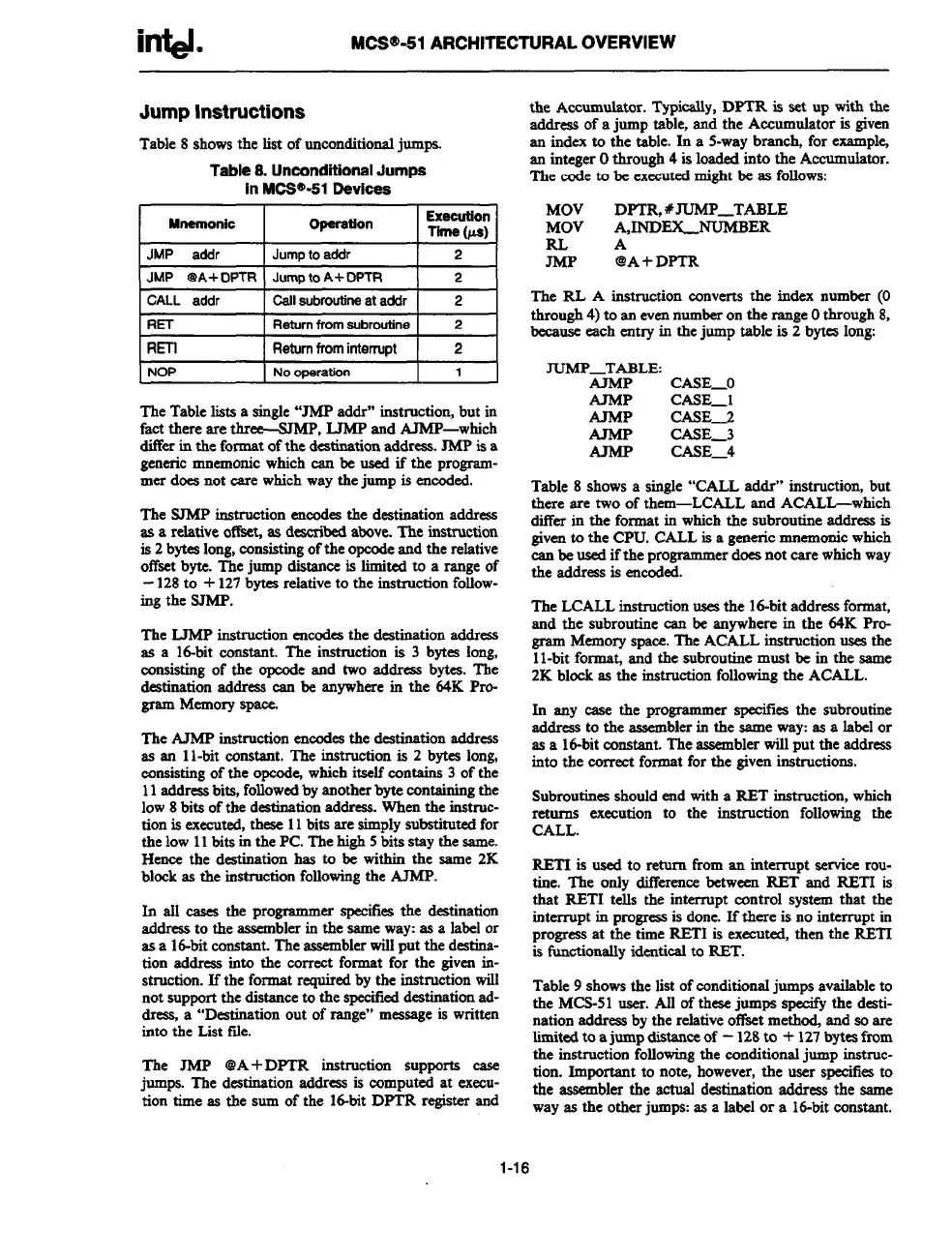
Table 8 shows the list of unconditional jumps.
Table 8. Unconditional Jumps
in MCW’-51 Oavices
I
Mnarnonic
I
Operation
Exeeution
Tilna (us)
I JMP addr
I Jumo to addr
121
JMP @A+ DPTR I Jump to A+ DPTR
I
2
CALL addr I Call subroutine at addr
2
1RET
I Returnfromsubroutine I z I
IRETI
I
Returnfrominterrupt I 2 I
NOP
No oparation
1
The Table lists a single “JMP addr” instruction, but in
fact there are three-SJMP, LJMP and AMP-which
differ in the format of the destination address. JMP is a
generic mnemonic which can be used if the program-
mer does not care which way the jump is eneoded.
The SJMP instruction eneodes the destination address
as a relative offset, as deaeribed above. The instruction
is 2 bytes long, eonsiating of the opeode and the relative
offset byte. The jump distance is limited to a range of
-128 to + 127bytes reIative to the instruction follow-
ing the SJMP.
The LJMP instruction eneodea the destination address
as a Id-bit constant. The instruction is 3 bytes long,
consisting of the opeode and two address bytes. The
destination address ean be anywhere in the 64K Pro-
gram Memory
SPSW.
The AJMP instruction encodesthe destination address
as an 1l-bit constant. The instruction is 2 bytee long,
eonaisting of the opode, which itself contains 3 of the
11address bits, followed by another byte containing the
low 8 bits of the destination address. When the instruc-
tion is executed, these 11bits are simply substituted for
the low 11bits in the PC. The high 5 bits stay the same.
Hence the destination has to be within the same 2K
block as the instruction following the AJMP.
In all eases the programmer specifies the de&nation
address to the assembler in the same way as a label or
as a id-bit constant. The assembler will put the destina-
tion address into the eormct format for the given in-
struction. If the format required by the instruction will
not support the distance to the specified destination rtd-
dresa, a “Destination out of range”
message is written
into the Lkt fde.
The JMP @A+ DPTR instruction supports ease
jumps. The destination address is computed at exeeu-
tion time as the sum of the lti-bit DPTR register and
the Accumulator. Typically, DPTR is set up with the
addms of a jump table, and the Accumulator is given
an index to the table. In a 5-way branch, for examplq
an integer Othrough 4 is loaded into the Accumulator.
The code to be executed might be ax follows
MOV
DPTR, #JUMP_TABLE
MOV
A,INDEX_NUMBER
RLA
JMP
@A+DPTR
The RL A instruction converts the index
number (O
through 4) to an even number on the range Othrough 8,
because each entry in the jump table is 2 bytee long:
~P_TABLE
MMP
CASE_O
AJMP
CASE_l
AJMP
CASE_2
AJMP
CASE_3
CASE_4
Table 8 shows a single “CALL addr” instruction, but
there are two of them-LCALL and ACALL-which
differ in the format in which the subroutine address is
given to the CPU. CALL is a generic mnemonic which
ean be used if the programmer does not care which way
the address is encoded.
The LCALL instruction uses the Id-bit address format,
and the subroutine ean be anywhere in the 64K Pro-
gram Memory space. The ACALL instruction uses the
1l-bit format, and the subroutine most be in the same
2K bkxk as the instruction following the ACALL.
In any case the programmer specifies the subroutine
address to the assembler in the same way as a label or
as a 16-bit constant. The assembler will put the address
into the correct format for the given instructions.
Subroutines should end with a RET instruction, which
returns execution to the instruction following the
CALL.
RETI is used to return from an interrupt service rou-
tine. The only difference between RET and RETI is
that RETI tells the interrupt control system that the
interrupt in progress is done. If there is no interrupt in
progress at the time RETI is executed, then the RETI
is functionally identical to RBT.
Table 9 shows the list of conditional jumps available to
the MCS-51 user. All of these jumps specify the desti-
nation address by the relative ot%et meth~ and so are
lindted to a jump distance of – 128to + 127bytes from
the instruction following the conditional jump instruc-
tion. Important to note, however, the user speeifies to
the assembler the actual destination address the same
way as the other jump as a label or a id-bit constant.
1-16