8XC51FXHARDWAREDESCRIPTION
6.7 Pulse Width Modulator Mode
Any or all of the five PCA modules can be pro-
p~ to be
a PukeWidthModulator.The PWM
output can be used to convert digital data to an analog
signalby simple externalcircuitry.The frequencyof the
PWM depends on the clock sources for the PCA timer.
With a 16 MHz crystalthe
maximum frequencyof the
PWM waveform is 15.6 KHz.
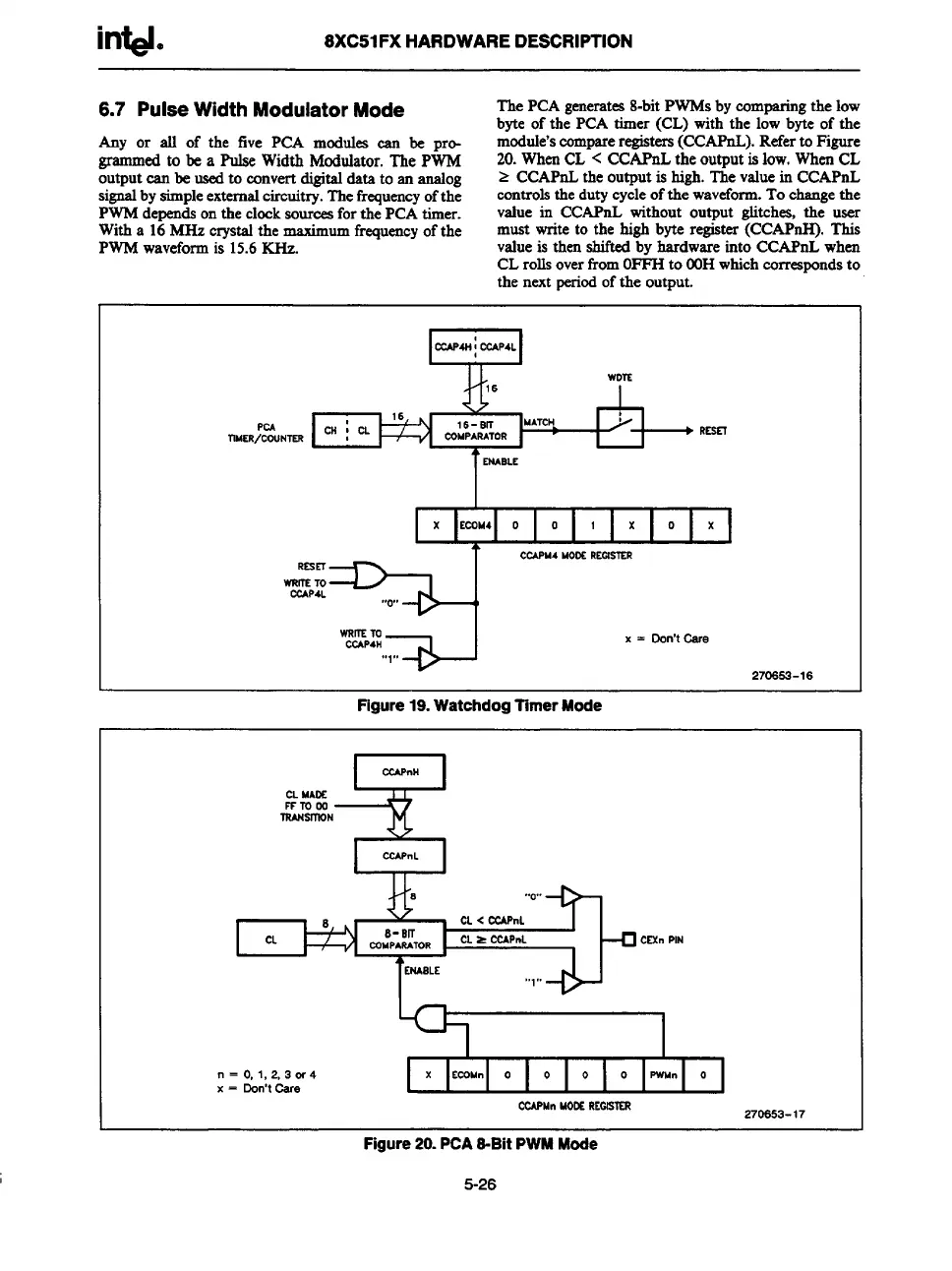
The PCA generates8-bit PWMS by comparing the low
byte of the PCA timer (CL) with the low byte of the
module’scompareregisters(CCAPnL). Referto Figure
20. When CL < CCAPnL the output is low. When CL
> CCAPnL the output is high. The value in CCAPnL
controls the duty cycle of the waveform.To change the
value in CCAPnL without output glitches, the user
must write to the high byte register (CCAPrsH). This
value is then shifted by hardwareinto CCAPnL when
CL rolls overfrom01%-I to WIHwhich correspondsto
the next periodof the output.
wDSS
PCA
1
I I* I
x KO144 o
I
o
I
1
I
x
I
o
I
x
I
CC4PM4 MODEREOISTER
RSsEl
WRm TO
CCAP4L
,, ,,
0
WRmm
CCAP4H
a
x = Don’t Cere
,, ,,
1
270653-16
Figure 19. Watchdog Timer Mode
&
CCAPnH
CL MADE
rrmoo
IRANSlllDN
“o,,
[ t
CL< CC4PnL
CL
8-Slf
rnMpARA70R
CL= ~PnL
~ CESnPIN
WBLE
,, ,,
1
n = O,1,2,3 w 4
x = Don’tCere
=
Cf2.APMnMOE REOUSXR
270653-17
I
Figure 20. PCA 6-Bit PWM Mode
5-26