EasyManua.ls Logo

Intel MCS 51 User Manual

Intel MCS 51
334 pages
To Next Page IconTo Next Page
To Previous Page IconTo Previous Page
Page #42 background imageLoading...
Page #42 background image
irltele
McS@-51PROGRAMMER’SGUIDE AND INSTRUCTION SET
INTERRUPTS:
In orderto use any of the interruptsin the MCS-51,the followingthree steps must be taken.
1. 3et the EA (enableall) bit in the IE register to 1.
2. Set the correspondingindividualinterrupt enablebit in the IE registerto 1.
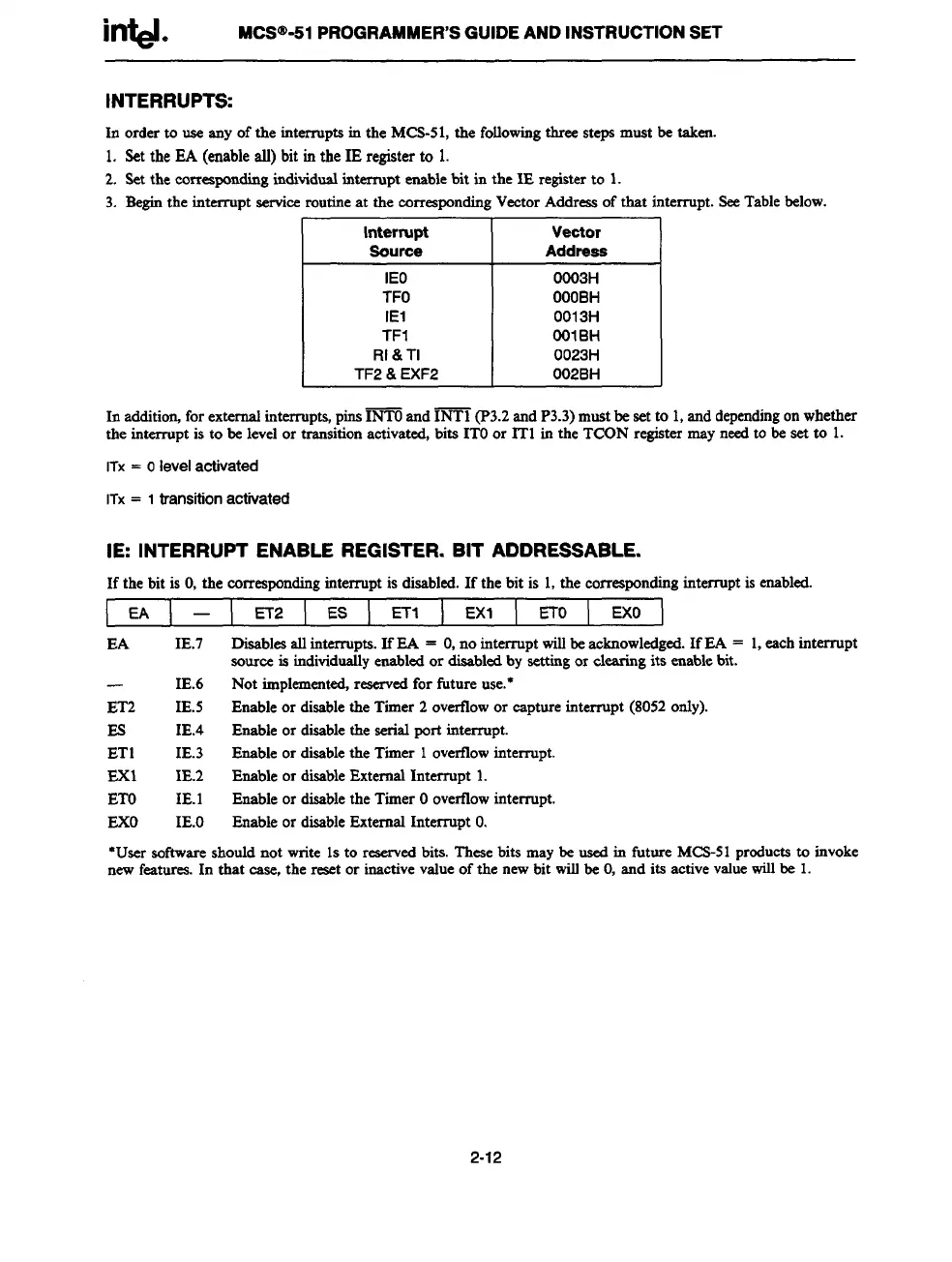
3. Beginthe
interruptserviceroutineat the em-respondingVectorAddressof that interrupt. SeeTablebelow.
I
Interrupt
I
Vector
Souroe
Address
I
IEO
TFO
IE1
TF1
RI &Tl
TF2 & EXF2
OO03H
OOOBH
O013H
OOIBH
O023H
O02BH
In addition,for extemafinterrupts,pins~ and INT1 (P3.2andP3.3)mustbe set to 1,anddependingonwhether
the intermpt is to be levelor transitionactivated,bits ITOor IT1 in the TCON register mayneedto be set to 1.
ITx = Olevelactivated
ITx= 1transitionactivated
IE: INTERRUPT ENABLE REGISTER. BIT ADDRESSABLE.
If the bit is O,the correspondinginterrupt is disabled.If the bit is 1,the correspondinginterruptis enabled.
EA ET2 ES ETl EX1 ETo
EXO
EA
IE.7 Disablesallinterrupts.IfEA = O,no interrupt willbeacknowledged.IfEA = 1,eachinterrupt
sourceis individuallyenabledor disabledby settingor elearin
g its enablebit.
IE.6 Not implemented,reservedfor future use.*
ET2 IE.5 Enableor disablethe Timer 2 overflowor capture interrupt (8052only).
Es
IE.4 Enableor disablethe serial port interrupt.
ET1
IE.3 Enableor disablethe Timer 1overtlowinterrupt.
EX1
IE.2 Enable or disableExternalInterrupt 1.
ETO
IE.1
Enableor disablethe Timer Ooverflowinterrupt.
EXO
IE.O Enableor disableExternal Interrupt O.
*Usersoftwareshouldnot write 1sto reserv
ed bits. Thesebits maybe usedin futore MCS-51preductsto invoke
newfeatures.In that case, the reset or inactivevalueof the newbit wiltbe O,and its activevaluewillbe 1.
2-12

Table of Contents

Question and Answer IconNeed help?

Do you have a question about the Intel MCS 51 and is the answer not in the manual?

Intel MCS 51 Specifications

General IconGeneral
Architecture8-bit
Number of Instructions111
Clock Speed12 MHz
Register Size8-bit
Internal RAM128 bytes
Internal ROM4 KB
External Memory64 KB
I/O Pins32
Timers2
Serial Port1
Interrupts5
Operating Voltage5V
UARTYes
Program Memory4 KB
RAM128 bytes
Instruction SetCISC

Summary

MCS® 51 Family of Microcontrollers Architectural Overview

THE MCS®-51 INSTRUCTION SET

Provides an overview of the MCS®-51 instruction set, optimized for 8-bit control applications.

Interrupt Structure

Overview of the 8051 interrupt structure, sources, and vectoring.

MCS® 51 Programmer’s Guide and Instruction Set

MCS®-51 INSTRUCTION SET

Provides a summary of the 8051 instruction set, including mnemonics and operands.

8051, 8052 and 80C51 Hardware Description

TIMER/COUNTERS

Describes Timer 0 and Timer 1, including operating modes and control registers.

8XC52/54/58 Hardware Description

8XC51FX Hardware Description

PORT STRUCTURES AND OPERATION

Details port structures, I/O configurations, and external memory access.

SERIAL INTERFACE

Covers serial port modes, framing error detection, and baud rate generation.

87C51GB Hardware Description

SPECIAL FUNCTION REGISTERS

Provides a map of the SFR space and their reset values.

SERIAL PORT

Details the serial port's modes, framing error detection, and baud rates.

INTERRUPTS

Covers interrupt sources, enable registers, and priority levels.

83C152 HARDWARE DESCRIPTION

Related product manuals