in~.
HARDWARE DESCRIPTIONOF THE 8051,8052 AND80C51
b
J&
loamm4AL
Oa
rnllo
CUTS
ar
ImLz
xrALl
-
a4
T
Suesl.
01
%s
270252-23
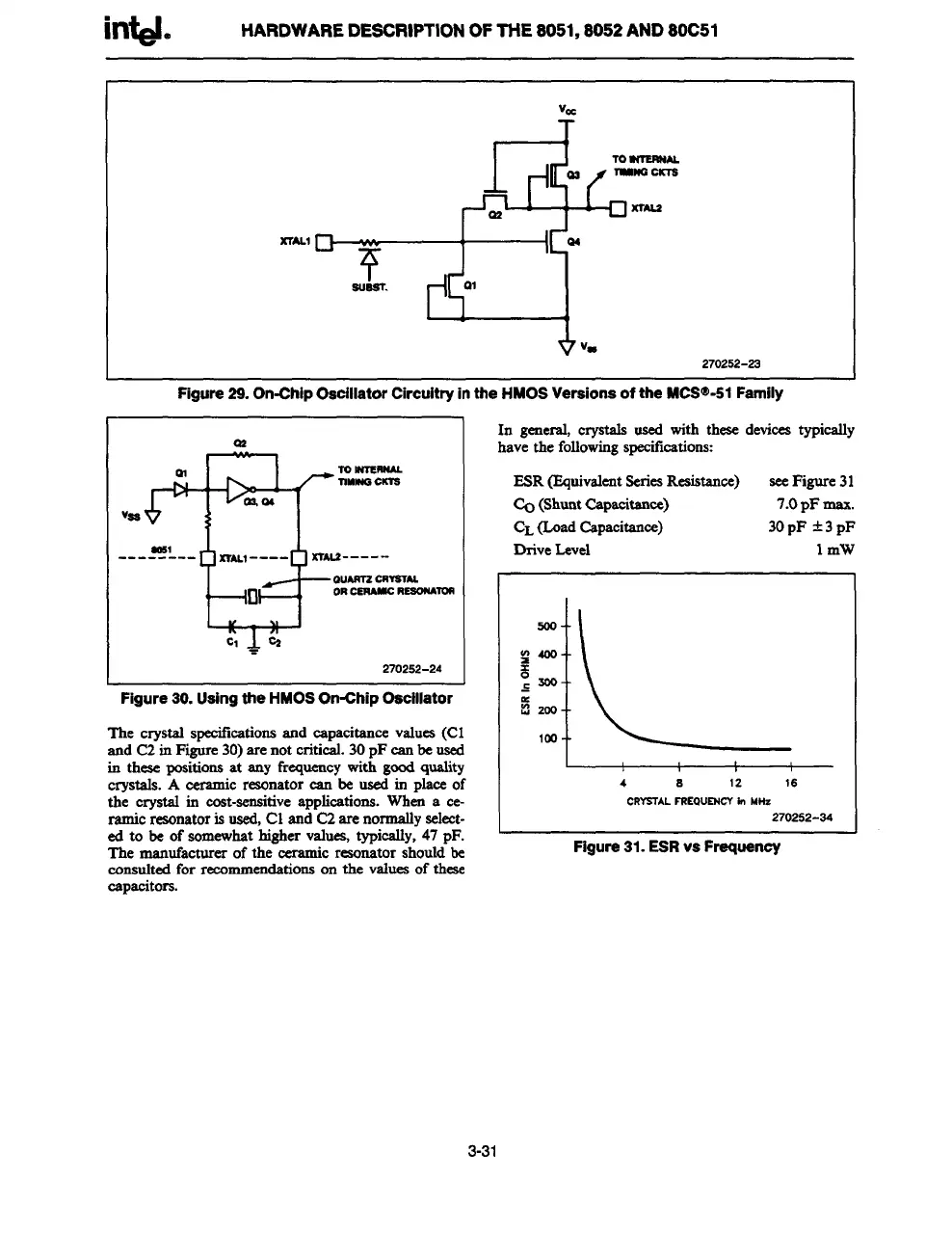
Figure29.On-ChipOsciiiatorCircuitryinthe HMOS Versions of the MCS@-51Famiiy
V=*”=
msl
--------
!-+=9
xrALl ----
xraLr -----
ouAnr2cRvalAL
0
ORC6RANICRESOWIOR
‘a%’
.
270252-24
Figure 30. Usingthe HMOS On-Chip Oeciiiator
The crvstal meeifkationa and cauacitanee values(Cl
and C2-inFi&re 30)arenot criti&l. 30pF canbe u&i
irr these positionsat any frequencywith goodquality
crystals. A
ceramic resonatorcan be used in place of
the crystal in cost-sensitiveapplications.When a ce-
ramic resonatoris used,Cl and C2arenormallyseleet-
edtobeofsomewhathighervaluea,typically,47pF.
The manufacturer of the ceramic resonator shouldbe
consultedfor recmnmcndationson the
vaiucs of thCSC
capacitors.
In general, crystals used with these devicestypically
have the followingspecifications:
ESR(EquivalentSeriesResistance)
seeFigure31
c20(ShuntCapacitance)
7.opFmax.
CL(bid ~pr$ei~ee)
30pF *3 pF
DriveLevel 1mW
4 a
12 16
CRYS7ALFSEQUEHCVin MHz
270252-34
—. - -—— -
Figure 31. ESR VSFr6!qUenOy
3-31