in~e
MCS@-51 ARCHITECTURAL OVERVIEW
states and phases for various kinds of instructions. Nor-
malIy two program fetches sre generated during each
machine cycle, even if the instruction being executed
doesn’t require it. If the instruction being executed
doesn’t need more code bytes, the CPU simply ignores
the extra fetch, and the Program Counter is not incre-
mented.
Execution of a one-cycle instruction (Figure 15A and
B) begins during State 1of the machine cycle when the
opcode is latched into the Instruction Register. A sec-
ond fetch occurs during S4 of the same machine cycle,
Execution is complete at the end of State 6 of this ms-
chine cycle.
The MOVX instructions take two machine cycles to
execute. No program fetch is generated during the see
ond cycle of a MOVX instruction. This is the ordy time
program fetches are skipped. The fetch/execute se-
quence for MOVX instructions is shown in Figure
15(D).
The fetch/execute sequences are the same whether the
Program Memory is internal or external to the chip.
Execution times do not depend on whether the Pro-
gram Memory is internal or external.
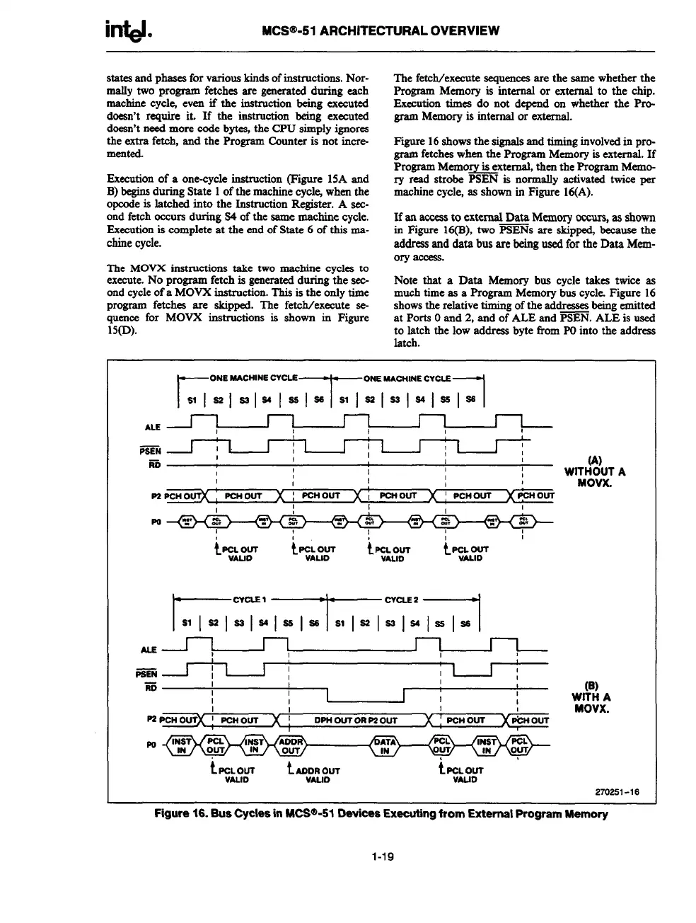
Figure 16shows the signals and timing involved in pro-
gram fetches when the Program Memory is external. If
Program Memo~xternsl, then the Program Memo-
ry read strobe PSEN is normally activated twice per
machine cycle, as shown in Figure 16(A).
If an access to external Data Memory occurs, as shown
in Figure 16(B), two PSENS are skippe$ because the
address and data bus are being used for the Data Mem-
ory access.
Note that a Data Memory bus cycle takes twice as
much time as a Program Memory bus cycle. Figure 16
shows the relative timing of the addresses being emitted
at Ports Oand 2, and of ALE and PSEN. ALE is used
to latch the low address bvte from POinto the address
latch.
r
ONE MACHINE CVCLS
T
ONE MACIUNE CYCLE
1
sl[a21s21s41aslss SIIS21S21S41SE 126
ALE
I
I
I
1
!
,
-N ~
I
I
I
1
1
I
L
r
I
1 I
1
1
I I
I
ro
1
I
I
I
1
1
WITH%)UT A
1
I
I
I
1
1
1
I
I
I
MOVX.
P2
PCH OUTX
PCH OUT
x
[
PCH OUT
x’
I
PCNOUT
1
I
I
1
t~::$m
t5i:F
ty;LL&T &T
G:v:m’lxm:m
)
I I
,
-N ~
I
1 1
I
1
I
1 I
1
E
I
1
I
I
(B)
I
I
I
I
I
WITH A
I
I
I
1
MOVX.
P2PcHc@(
! PCHOUT
x!
OPH OUT OR P2 OUT
x:
PCH OUT )( PWOUT
t P&m&T iAC:O&UT
2702!31 -16
Figure 16. Bus Cycles in MCS@-51 Oevices Extilng irom External Program Memory
1-19