i~.
8XC51FXHARDWAREDESCRIPTION
Any of these three conditions will block the generation
of the LCALL to the interruptservice routine. Condi-
tion 2 ensures that the instruction in progress will be
mmpleted before vectoringto any seMce routine. Con-
dition 3 ensures that if the instruction in progress is
RETI or any write to IE or 1P, then at least one more
instruction will be executed beforeany interruptis vec-
tored to.
The polling cycle is repeatedwith each machine CYC1%
andthe values polled arethe values that werepresentat
S5P2 of the previous machine cycle. If the interrupt
fig for a Zeve/-sensitiveexternal interrupt is active but
not being responded to for one of the above conditions
and is not still active when the blocking wndition is
removed, the denied interrupt will not be serviced. In
other worda, the fact that the interrupt flag was once
active but not serviced is not remembered.Every poll-
ing cycle is new.
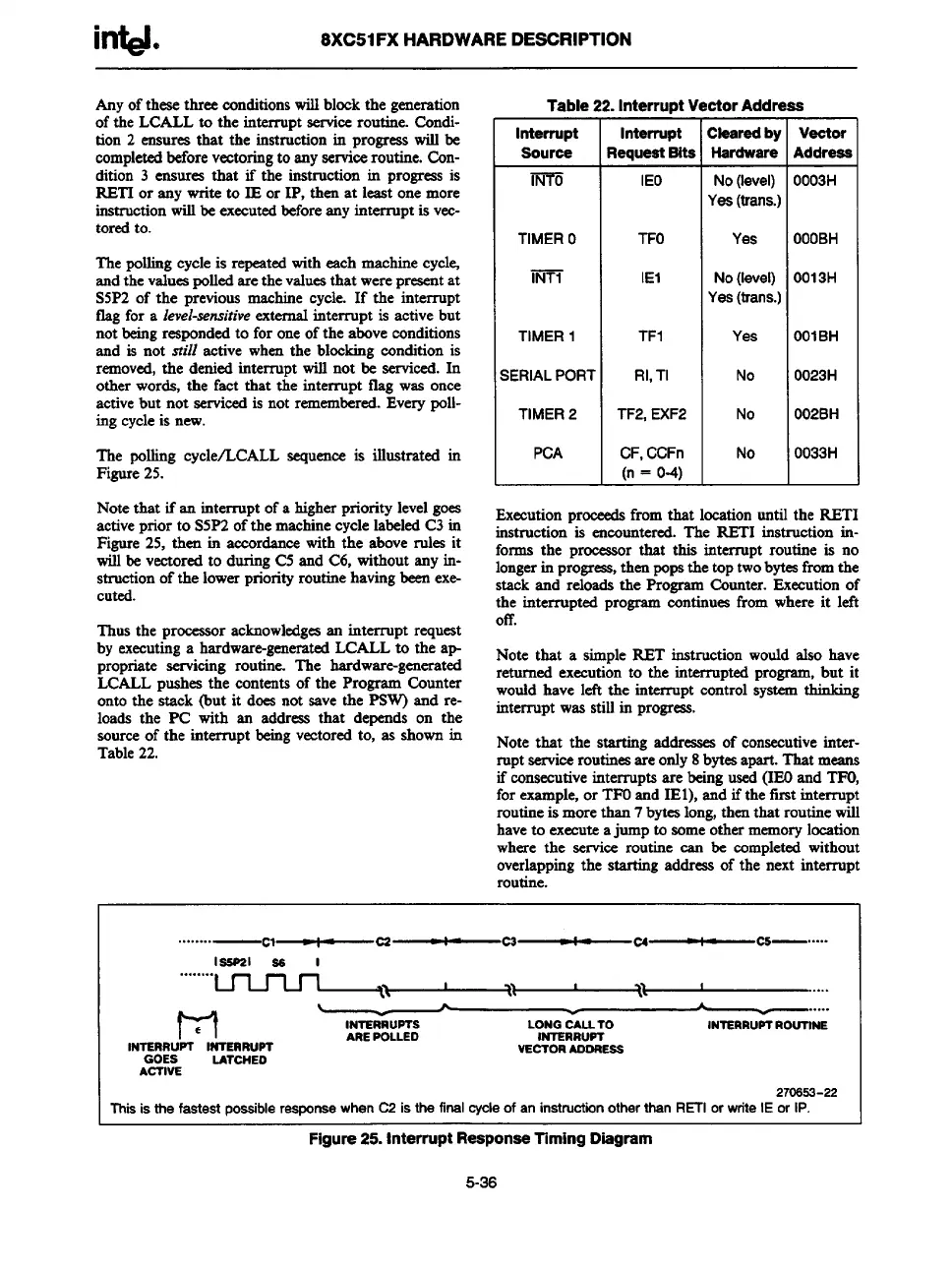
The polling cycle/LCALL sequence is illustrated in
Figure 25.
Note that if an interrupt of a higher priority level goes
activeprior to S5P2 of the machine cycle labeled C3 in
Figure 25, then in awordance with the above rules it
will be vectored to during C5 and C6, without any in-
struction of the lower priorityroutine having been exe-
cuted.
Thus the proceasor acknowledges an interrupt request
by executing a hardware-generatedLCALL to the ap
propriate servicing routine. The hardware-generated
LCALL pushes the contents of the Program Counter
onto the stsck (but it does not save the P3W) and re-
loads the PC with an address that depends on the
source of the interrupt being vectored to, as shown in
Table 22.
Table
Interrupt
Source
m
TIMERO
m
TIMER1
;ERIALPOR1
TIMER2
PCA
. Interrupt ~
Interrupt
?equeetBite
IEO
TFO
IEI
TF1
Rl,TI
TF2,EXF2
CF,CCFn
(n= O-4)
ctorAddn
LXearedby
l+srdware
No (level)
Yea (trans.)
Yes
No (level)
Yea (trans.)
Yes
No
No
No
la
7
Veotor
Address
OO03H
OOOBH
O013H
OOIBH
O023H
O02BH
O033H
Execution proceeds from that location until the RETI
instructicm-is enwuntered. The RETI instruction in-
forms the proceasor that this intemupt routine is no
longerin progress,then pops the top twobyteafkomthe
stack and reloads the Program Counter. Execution of
the interrupted program wntinuee from where it left
off.
Note that a simple RET instruction would also have
returned execution to the interrupted program, but it
would have left the interrupt control system thinking
interruptwas still in profyess.
Note that the starting addresses of consecutive inter-
ruptserviceroutines areonly 8 bytes apart.That means
if consecutive interrrmtsarebeing used (IEOand TFO.
for example, or TFO&d IEl), ma ifthe’first interrupt
routineis more than 7 bytes long, then that routine will
have to execute ajump to some othermemory location
where the service routine can be wmpleted without
overlapping the starting address of the next interrupt
laaPal Se I
““””””””~~~~--
f-1
.....
6
INTERRUPTS
LONG CALLTO
INTERRuPT ROUTINE
INTERRUPT INTERRUPT
ARE POLLED
INTSRRUPT
GOES
VECTOR AOORESS
LATCHEO
ACTIVE
270SS2-22
This
is the fastest possibleresponsewhen C2 is the finalcycleof an instructionotherthen REH or writeIE or 1P.
Figure 25. Interrupt Response Timing Diagram
5-36