i~.
8XC51FXHARDWAREDESCRIPTION
If two requests of different priority levels are received
simultaneously, the request of higher priority level is
servieed. If requests of the same priority level are re-
ceived simultaneously,an internalpolling sequence de-
termines which request is servieed. Thus within each
prioritylevel there is a second prioritystructure deter-
mined by the potling sequence shown in Table 19.
Note that the “priority within level” structure is only
used to resolvesimultaneous requestsof thesameprian”-
ty level.
Table 19. Interrupt Priority
within Level Polling Seauence
1(Highest)
INTO
2
TimerO
3
m
4
Timer1
5
PCA
6
SerialPort
7(Lowest) Timer2
8XC51FXInterrupt Priority Struoture
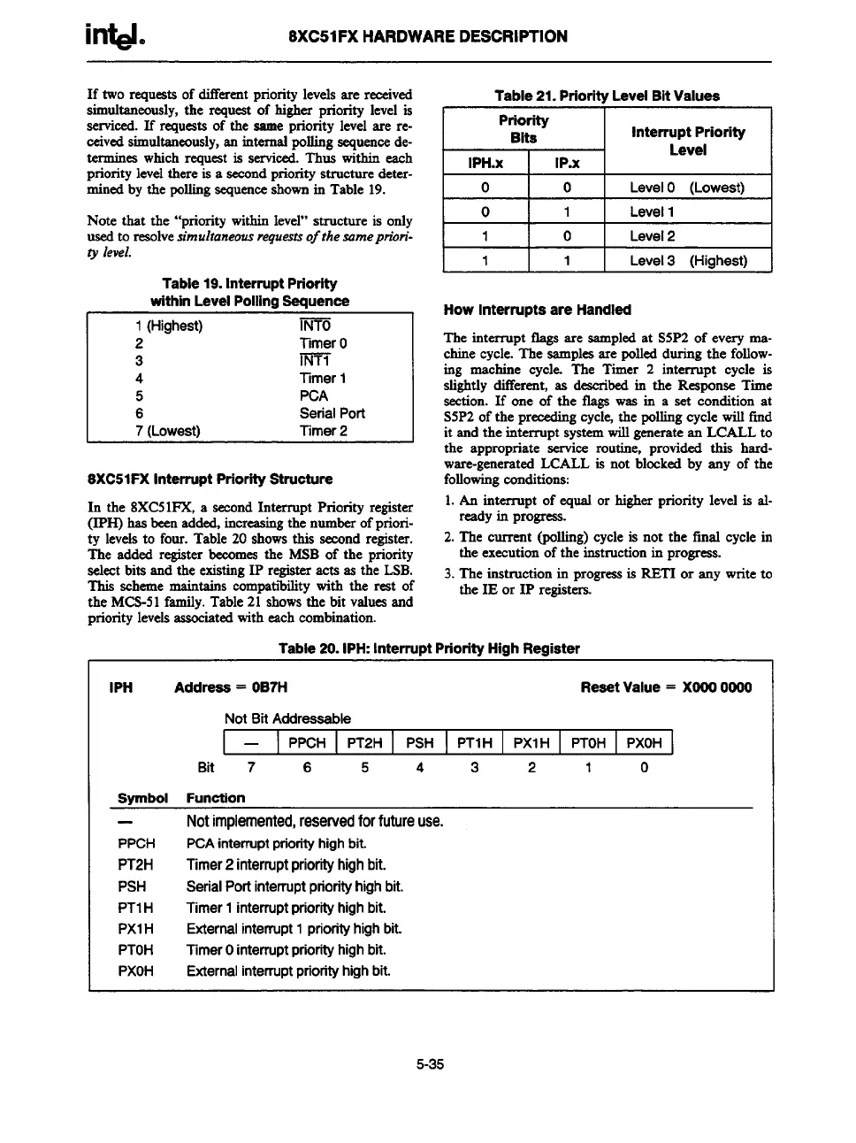
In the 8XC51FX, a second Interrupt Priority register
(IPH) has been added, increasingthe number of priori-
ty levels to four. Table 20 shows this second register.
The added registerbecomes the MSB of the priority
select bits and the existing 1P registeracts as the LSB.
This scheme maintains eotnpatibility with the rest of
the MCS-51 family. Table 21 shows the bit values and
priority levels associatedwith each combination.
Table 21. Priority Level Bit Values
Priority
Bits
Interrupt Priority
Level
IPH.x IP.X
o
0
LevelO (Lowest)
1o11
I Levell
I
11 I O I Level2
I
1111
I
Leve13 [Hiahest) I
How Interrupts are Handled
Theinterruptflagsare sampled at S5P2 of every ma-
chine cycle. The samples are polled during the follow-
ing machine cycle. The Timer 2 interrupt cycle is
slightly different, as described in the Response Time
section. If one of the tlags was in a set condition at
S5P2 of the precading cycle, the polling cycle will fmd
it and the interrupt system will generatean LCALL to
the appropriate serviee routine, provided this hard-
ware-generatedLCALL is not blocked by any of the
following conditions:
1. An interrupt of equal or higher priority level is al-
ready in
progress.
2. The current (polling) cycle is not the final cycle in
the execution of the instruction in progress.
3. The instruction in nroaressis RETI or anv write to
the IE or 1P regiat~rs.-
Table 20. IPH: Interrupt Priority High Register
IPH
Address = OB7H
Reeet Value = XOOO0000
NotBit Addressable
—
PPCH PT2H
PSH PTIH PXIH
PTOH PXOH
Bit 7 6
5 4 3 2
1 0
Svmbol Funotion
—
PPCH
PT2H
PSH
PTIH
PXIH
PTOH
PXOH
Notimplemented,reservedforfutureuse.
PCA
interrupt priority high bit.
Timer2interruptpriorityhighbit.
SerialPortinterruptpriorityhighbit.
Timer1interruptpriorityhighbit.
Externalinterrupt1priorityhighbit.
TimerOinterruptpriorityhighbit.
Externalinterruptpriorityhighbit.
5-35