i~.
HARDWARE DESCRIPTION OFTHE 8051,8052 AND 80C51
TIMER1
TIMER2
OVERFLOW
OVERFLOW
!?
WRITS
+2
TO —
SMOD
SBUF
SMOD
=0
=1
20s1INTERNALBUS
TSS
TXD
RCLK----
IFFH
RXD
LOAD
SBUF
*
SSUF
READ
SSUF
lx
@oclq
I I
I
I
I
IWWTSTOSSUF
sEND
OATA
SIPF r
sNln
1
1 0
I
I 00
z
m
1
m
r 03 1 0s 1 D5 r 0s 1 n7 1
+1’1
rRANsMrT
~L
1!
STARTSIT
STOPBtl
-lsnEsm
l-++++++:
.S
RXO
MT”
RECEIVE ● TM=-—=
STOPOIT
Blwf
RI
270262-16
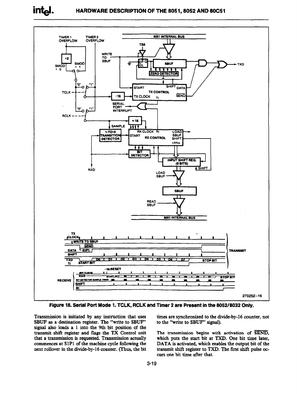
Figure 18. Serial Port Mode 1. TCLK, RCLK and TTmer2 are Preaent in the 8052/8032 Only.
T
rammissionis initiated by any instruction that oses
timesare synchronisedto the divide-by-16counter, not
SBUFas a destinationregister. The “write to SBUF”
to the “write to SBUF”signal).
sid * IOSdSa 1 into the 9th bit positionof the
transmit shift registerand flags the TX Control unit
The transmission begins with activation of SEND,
that a transmissionis requested.Tmnsmiss
ionaotually whichputs the start bit at TXD. One bit time later,
commencesat SIP1 ofthe machinecyclefollowingthe
DATAisactivated,whichenablesthe output bit ofthe
nextrolloverin the divide-by-16counter. (Thus,the bit
transmitshift registerto TXD.The first shift pulsecc-
curs onebit time after that.
3-19