i~e
8XC51FXHARDWAREDESCRIPTION
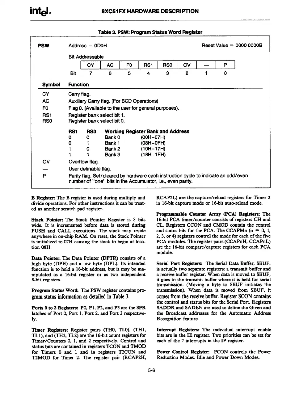
Table 3. PSW:Program Statua Word Regiater
Psw
Address= ODOH
ResetValue= 0000OOOOB
BitAddressable
CY AC FO
RSI RSO Ov I — P
Bit 7
6
5 4 3 2
1
0
Symbol Function
CY Carryflag.
AC AuxiliaryCarryflag. (For
BCDOperations)
FO
FlagO.(Availabletotheuserforgeneralpurposes).
RS1 Registerbankselectbit1.
RSO
RegisterbankselectbitO.
RS1 RSO Working Register Sank and Addreee
o 0
BankO (OOH-07H)
o
1 Bank1 (08H-OFH)
1 0 Bank2
(1OH-17H)
1
1
Bank3
(18H-l FH)
Ov
Overflowflag.
—
Userdefinableflag.
P Parityflag.Set/clearedbyhardwareeachinstructioncycleto indicateanodd/even
numberof “one” bitsintheAccumulator,i.e.,evenparity.
B RegisteE The B registeris used during multiply and
divide operations.For other instructions it can be treat-
ed as another scratchpad register.
Stack Pointer: The Stsek Pointer Register is
8 bits
wide. It is incremented before &ta is stored during
PUSH and CALL executions. The stsek may reside
~ywhere in
on-chipR4M.Onreset, the Stack Pointer
is initialized to 07H causing the stack to begin at loca-
tion 08H.
Data PointeE The Data Pointer (DPTR) consists of a
high byte (DPH) and a low byte (DPL). Its intended
function is to hold a 16-bit address, but it may be ma-
nipulated as a Id-bit register or as two independent
8-bit registers.
Program Status Word: The PSW registercontains pr-
gram
statusinformationasdetailedin Table3.
Ports Oto 3 Registers: PO,Pl, P2, and P3 arethe SFR
latches of Port O,Port 1, Port 2, and Port 3 respective-
ly.
RCAP2L) are the capture/reload registemfor Timer 2
in Id-bit capture mode or Id-bit auto-reloadmode.
Pmgmmmable Counter Array (PCA) Re@ters: The
16-bitPCA timer/counter cxmsistsof registersCH and
CL. Registers CCON and CMOD contain the control
and status bits for the PCA. The CCAPMn (n = O, 1,
2, 3, or4) registerscontrolthe mode for each of the five
PCA modules. The registerpairs(CCAPnH, CCAPnL)
are the id-bit compare/capture registersfor each PCA
module.
Serial Port Registers: The Serial Data ButTer,SBUF,
is actually two separateregisters:a transmit buffer and
a receivebutYerregister.When data is moved to SBUF,
it goes to the transmit buffer where it is held for serial
transmission. (Moving a byte to SBUF initiates the
transmission). When data is moved from SBUF, it
comesfromthereceivebtier.RegisterSCONcontains
the control and status bits for the SerialPort. Registers
SADDR and SADEN are used to definethe Given and
the Broadcast addresses for the Automatic Address
Recognition feeture.
Timer
Registers:Registerpairs (THO,TLO),(’THL
Interrupt Regiatam: The individual interrupt enable
TL1), and (TH2, TL2) arethe id-bit count registersfor
bits are in the IE register.Two prioritiescan be set for
Timer/Counters O, 1, and 2 rqeetively. Control and
each of the 7 interrupts in the 1P register.
statusbita arecontainedin registersTCON and TMOD
for Timers O and 1 and in registers T2CON and
Power Control Register: PCON controls the Power
T2MOD for Timer 2. The register pair @CAF2H,
Reduetion Modes. Idle and Power Down Modes.
5-6