in~.
87C51GB HARDWARE DESCRIPTION
User softwareshouldnot write 1’sto these unimple-
mented locations,since they may be used in future
MCS-51productsto invokenewfeatures.In that case
the reset or inactivevaluesof the newbits willalways
be O,and their activevalueswillbe 1.
The functionsof the SFRSsre outlinedbelow. More
informationonthew of apecificSFRSforeachperiph-
eral is includedin the descriptionof
thatperipheral.
AccumsdatoRACC is the Accumulator register. The
mnemonics for Accumulator-Specific instructions,
however,referto the Accmrmdatoraimplyas A.
B Register:The B registeris usedduringmultiplyand
divideoperations.For other instructionsit canbe treat-
ed as anotherscratchpad register.
StackPointaE The Stack Pointer Register is 8 bits
wide. It is incrementedbefore data is stored during
PUSH and CALL execution. The stack may reside
anywherein on-chipR4M. Onreset, the StackPointer
is initializedto 07Hcausingthe stack ta beginat loca-
tion 08H.
Data PoisItec The Data Pointer (DPTR) consistsof a
high byte (DPH) and a low byte (DPL). Its intended
fimctionis to holda 16-bitaddress,but it maybe ma-
nipulated as a Id-bit register or as two independent
8-bitregisters.
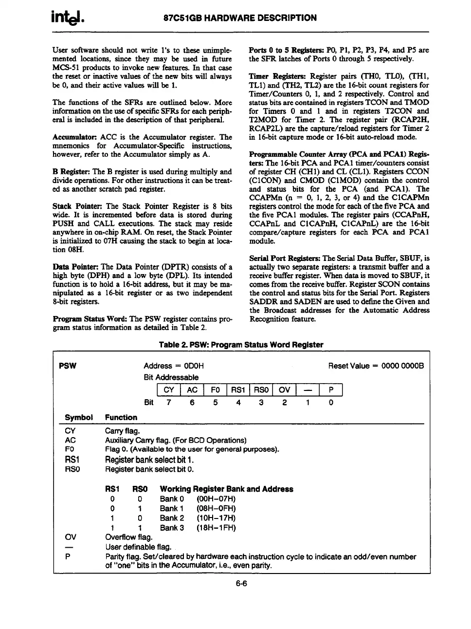
Rogrsun Status Word:The PSWregistercontainspro-
- ststus informationas detailedin Table2.
Ports Oto 5 Registers:PO,Pl, P2, P3, P4, and P5 are
the SFR latches ofPorts Othrough5 respectively.
Timer Registers: Regista pairs (’IWO,TLO), (THl,
TL1)and (TH2,TL2)are the id-bit count registersfor
Timer/Counters O,1, and 2 respectively.Control and
statusbits are containedinregistersTCONand TMOD
for Timers O and 1 and in registers T2CON and
T2MOD for Timer 2. The register pair (RCAP2H,
RCAF2L)are the capture/reloadregistersfor Timer 2
in id-bit capture modeor 16-bitauto-reloadmode.
Prosrsrnmsbleauntar AITSY~CA =d PCA1)Re@-
tera:The id-bit PCAandPCA1timer/counters consist
of registerCH (CH1)and CL (CL1).RegistersCCON
(CICON) and CMOD (CIMOD) contain the control
and status bits for the PCA (and PCA1). The
CCAPMn(n = O, 1, 2, 3, or 4) and the CICAPMn
registerscontrolthe modefor eachofthe fivePCA and
the fivePCA1modules.The registerpairs (CCAPnH,
CCAPnL and CICAPnH, CICAPnL) are the lti-bit
compare/capture registers for each PCA and PCA1
module.
SerisdPort Registers:TheSerialData Buffer,SBUF,is
actuallytwo separate registers:a transmit buffer and a
receivebufferregister.Whendata is movedto SBUF,it
comesfromthe rexive buffer.RegisterSCONcontaina
the controland status bits forthe SerialPort. Registers
SADDRand SADENare usedto definethe Oivenand
the Broadcast addreaaesfor the Automatic Address
Recognitionfeature.
Psw
Address= ODOH ResetValue= 0000OOOOB
BitAddressable
CY ] AC FO RS1 RSO Ov — P
Bit 7 6 5 4 3 2 1 0
Symbol Function
CY
Carryflag.
AC AuxiliaryCarryflag.(ForBCDOperations)
FlagO.(Availabletotheuserforgeneralpurposes).
& Registerbankselectbit1.
RSO
Registerbankselectbito.
RS1
RSO WorkingRegisterBankandAddress
o 0
BankO (OOH-07H)
01
Bank1 (08H-OFH)
1 0
Bank2 (1OH-17H)
1 1
Bank3 (18H-l FH)
Ov Overflowflag.
—
Userdefinableflag.
P
Parityflag.Set/clearedbyhardwareeachinstructioncycletoindicateanodd/evennumber
of“one”bitsintheAccumulator,i.e.,evenparity.
6-6