intele
83C152 HARDWARE DESCRIPTION
3.3.2
SDLC Frame Format
The
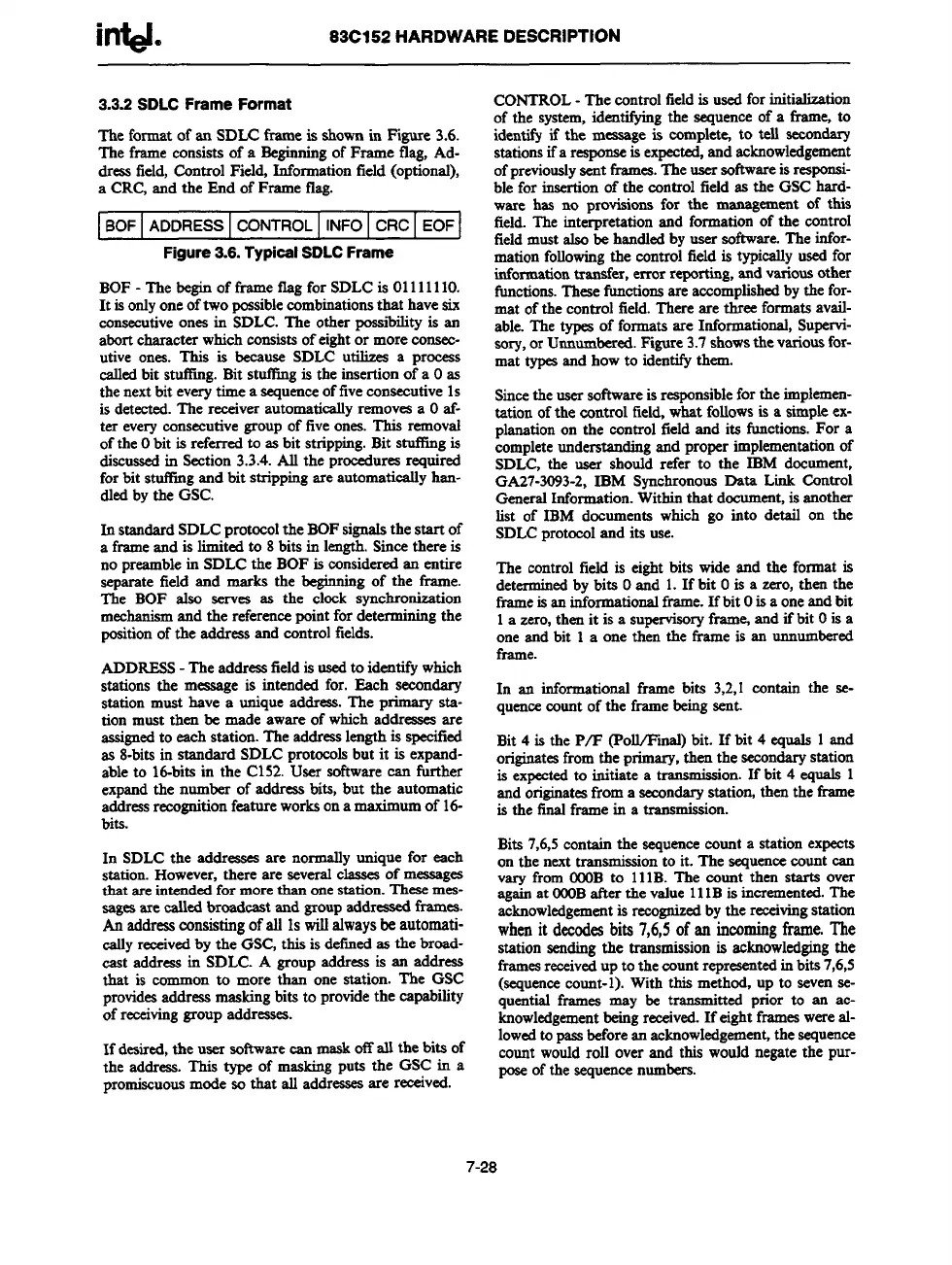
format of an SDLCframe is shownin Figure 3.6.
The frame consistsof a Beginningof Frame flag, Ad-
dressfield,Control Field, Informationfield (optional),
a CRC,and the End of Frameflag.
I BOFI ADDRESS I CONTROL I INFO I CRC I EOFI
Figure 3.6. Typical SDLC Frame
BOF- The beginof frame flag forSDLCis0111 1110.
It isonlyoneoftwo possiblecombinationsthat havesix
consecutiveonesin SDLC.The other possibilityis an
abortcharacter whichconsistsof eightor moreconsec-
utive ones. This is because SDLC utilizes a process
calledbit stutling. Bit stuffingis the insertionof a Oas
thenextbit everytime a sequenceoffiveconsecutive1s
is detected.The receiverautomaticallyremovesa Oaf-
ter everyconsecutivegroupof fiveones.This removrd
ofthe Obit is referred to as bit stripping.Bit stuffingis
discussedin Section3.3.4.All the proceduresrequired
forbit stutlingand bit strippingare automaticallyhan-
dledby the GSC.
In standardSDLCprotocolthe BOFsignalsthe start of
a frameand is limitedto 8 bits in length.Sincethere is
no preamblein SDLCthe BOF is consideredan entire
separate field and marks the &ginningof the ffame.
The BOF also scrv= as the clock synchronisation
mechanismand the referencepointfor determining
g the
positionof the addreasand controlfields.
ADDRESS-The addressfieldis usedto identifywhich
stations the message is intended for. Each secondary
station must have a uniqueaddress.The primary sta-
tion must then be made aware of whichaddresses are
assignedto eachstation. The addresslengthis specitied
as 8-bitsin standard SDLCprotocolsbut it is expand-
able to 16-bitsin the C152.User softwarecan further
expandthe number of addressbits, but the automatic
addressrecognitionfeatureworksona maximumof 16-
bits.
In SDLCthe addressesare normallyunique for each
station.However,there are severalclassesof messages
that are intendedfor morethan onestation.Thesemes-
sagesare calledbroadcast and groupaddressedframea.
An addressconsistingofall 1swillalwaysbe automati-
callyreceivedbythe GSfGthis is deilnedas the broad-
cast addreasin SDLC. A group address is an ad&ess
that is
commonto more than one station. The GSC
providesaddr$ssmaskingbits to providethe capability
of receivinggroupaddresses.
If desired,the user softwarecan maskoffall the bits of
the address.This type of maskingputs the GSC in a
promiscuousmodeso that all addressesare received.
CONTROL- The controlfieldis usedforinitialization
of the system,iden~g the sequenceof a frame to
identfi if the messageis complem to teUsecondary
stationsifa response
isexpected,andacknowledgement
ofpreviouslysentframes.Theusersoftwareis responsi-
ble for ‘mscrtionof the controlfield as the GSC hard-
ware has no provisionsfor the managementof this
field.The interpretation and formationof the control
fieldmustalso be handledby user software.The infor-
mationfollowingthe controlfieldis typicallyusedfor
informationtransfer, error reporting,rmdvariousother
functions.Thesefunctionsare accomplishedbythe for-
mat ofthe controlfield.There are three formatsavail-
able.The types of formats are Informational,Supervi-
sory,or Unnumbered.Figure3.7showsthevariousfor-
mat typesand how to identifythem.
Sincetheusersoftwareisresponsiblefor the implemen-
tation ofthe control field,what followsis a simpleex-
planationon the control fieldand its timctions.For a
completeunderstandingand proper implementationof
SDLC,the user should refer to the IBM document,
GA27-3093-2,IBM SynchronousData Link Control
GeneralInformation.Withinthat document,isanother
list of IBM documents which go into detail on the
SDLCprotocoland its use.
The control field is eight bits wide and the fomnatis
determined by bits Oand 1. If bit Ois a zero, then the
frameis aninformationalframe.If bit Oisa oneandbit
1a zero,then it is a supervisoryframejand if bit Ois a
oneand bit 1 a one then the frame is an unnumbered
frame.
In an informationalframe bits 3,2,1 contain the se-
quencecountof the framebeingsent.
Bit 4 is the P/F (Poll/Final) bit. If bit 4 equals 1 and
originatesfromthe primary,then the
secondarystation
is expectedto initiate a t
ransmkaion.If bit 4 equals 1
andoriginatesfrom a secondarystatiorhthenthe frame
is the finalframe in a transmission.
Bits 7,6,5containthe sequencecmmta station expects
on the nexttransmissionto it. The sequencecount can
vw from OOOBto 11lB. The count then starts over
againat OOOBatler the value11IB is incremented.The
acknowledgementis recognizedbythe receivingstation
whenit decodesbits 7,6,5of an incomingframe. The
station sendingthe transmissionis acknowledgingthe
framesreceivedupto the countrepresentedinbits7,6,5
(sequencecount-l). With this method, up to sevense-
quential framea may be trsnami
tied prior to an ac-
knowledgementbeingreceived.If eightframeswereal-
lowedtopassbeforean acknowledgement,thesequence
count wouldroll over and this wouldnegatethe pur-
poseof the sequencenumbers.
7-28