83C152 HARDWARE DESCRIPTION
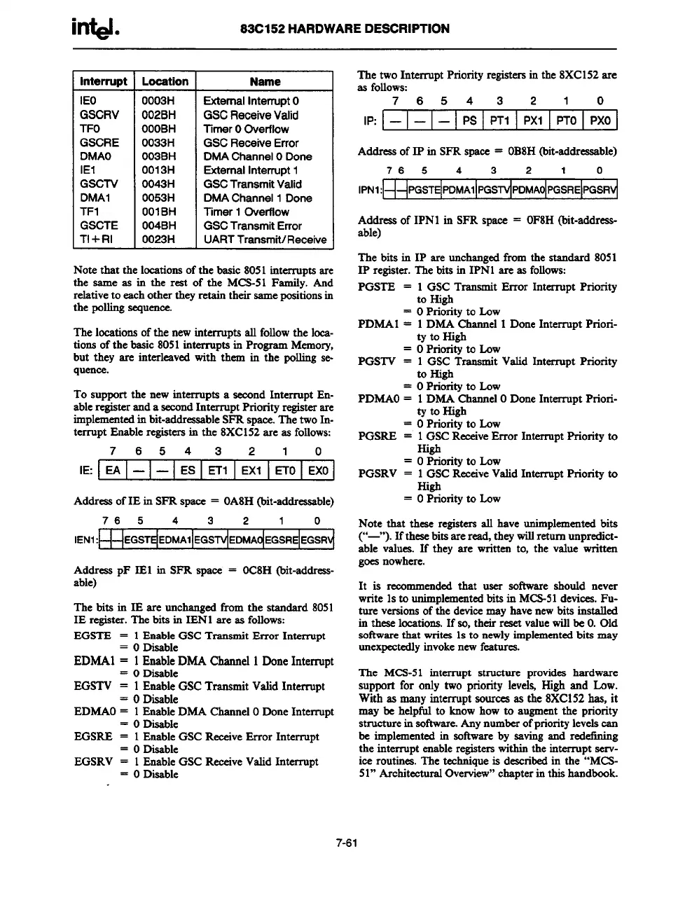
Interrupt
IEO
GSCRV
TFO
GSCRE
DMAO
IE1
GSCTV
DMA1
TF1
GSCTE
TI+RI
Location
OO03H
O02BH
OOOBH
O033H
O03BH
O013H
O043H
O053H
OOIBH
O04BH
O023H
Name
ExternalInterruptO
GSC Receive Valid
Timer OOverflow
GSC Receive Error
DMA ChannelODone
ExternalInterrupt1
GSCTrartsmitValid
DMA Channel 1 Done
Timer 1 Overflow
GSC TransmitError
UARTTransmit/Receive
Note that the
locationsof the basic 8051 interruut.sare
the same as in the reat of the MCS-51Fsrnil~. And
relativeto eachother they retsin their samepositionsin
the pollingsequence.
The locationsof the newinterrupts all followthe locs-
tion.sof the basic 8051interruptain Program Memory,
but they are interleavedwith them in the pollingse-
quence.
To support the new interrupts a second Interrupt En-
ableregisteranda
secondInterrupt Priority registerare
implementedinbit-addressableSFRspace.ThetwoIn-
terrupt Enableregistersin the 8XC152are as follows:
7 6543 2 1 0
IE: EA
— —
ES ETl
EX1 ETo EXO
Addressof IE in SFRspace = OA8H(bit-addressable)
76 5
4 3 2 1
0
lENl:U4EGSTdEDMAllEGS~ EDMAo!EGSREtEGsRvi
Address pF IEl in SFR space = OC8H(bit-address-
able)
The bits in IE are unchangedfrom the stsndsrd 8051
IE register.The bits in IEN1 are as follows:
EGSTE = 1EnableGSCTransmit Error Interrupt
= ODisable
EDMA1 = 1EnableDMA Channel 1DoneInterrupt
=
O Disable
EGSTV = 1 EnableGSCTrsnsmit Valid Interrupt
= ODisable
EDMAO= 1Emble DMA ChannelODone Interrupt
= ODisable
EGSRE = 1EnableGSCReceiveError Interrupt
= ODisable
EGSRV = 1EnableGSC ReceiveValidInterrupt
= ODisable
The two Interrupt Priorityregistersin the 8XC152are
as follows:
76543 2 1 0
1P: — — —
Ps PT1 Pxl
PTo Pxo
Addressof IP in SFR space = OB8H(bit-addressable)
76 5
4 3 2
1 0
IPN1:
Addressof IPN1 in SFR space = OF8H(trit-sddress-
able)
The bits in 1P are uncharuzedfrom the standard 8051
1Pregister.Thebits in IP~l areas follows:
PGSTE =
.
PDMAI =
.
PGSTV =
=
PDMAO=
.
PGSRE =
.
PGSRV =
.
1 GSC Transmit Error Interrupt Priority
to High
o Priorityto Low
1DMA Channel1 DoneInterrupt Priori-
ty to High
o Priorityto Low
1 GSC Transmit Valid Interrupt Priority
to High
o Priorityto Low
1DMA ChannelODoneInterrupt Priori-
ty to High
o Priorityto Low
1GSCReceiveError Interrupt Priority to
High
o Priorityto Low
1GSCReeeiveValidInterrupt Priority to
High
o Priorityto Low
Note that these registersall have unimplementedbits
(“-”). If thesebitsare r~ theywillreturn unpredict-
able values.If they are written to, the value written
goesnowhere.
It is recommendedthat user software should never
write 1sto unimplementedbits in MCS-51devices.Fu-
ture versionsof the devicemay havenewbits instslled
in theseloestiorta.If so, their reset valuewillbe O.Old
softwarethat writes 1sto newlyimplementedbits may
unexpectedlyinvokenewfeatures
The MCS-51interrupt structure provides hardware
support for only two priority levels High and Low.
With as manyinterrupt sourcesas the 8XC152has, it
may be helpful to knowhow to augmentthe priority
structurein software.Anynumberofprioritylevelscan
be implementedin softwareby savingand redefining
the interrupt enableregisterswithinthe interrupt serv-
iee routines.The techniqueis deacribedin the “MCS-
51”ArchitecturalOverview”chapterinthis handbook.
7-61