Section 4: Theory of operation Model 2651A High Power System SourceMeter® Instrument Reference Manual
4-6 2651A-901-01 Rev. A / March 2011
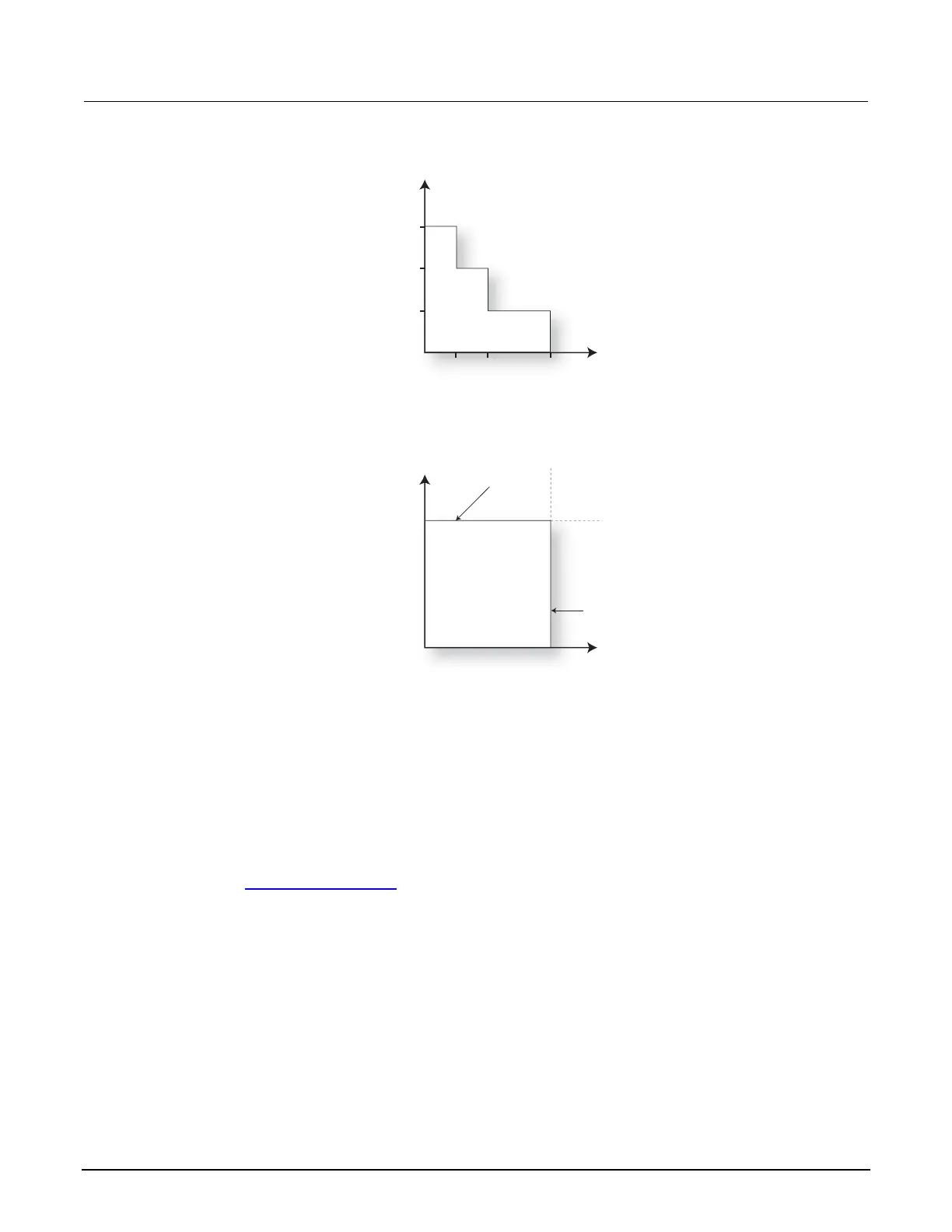
Figure 71: Models 2651A I-source boundaries
V-measure
40 V
20 V
10 V
10.1 A
20.2 A
5.05 A
A: Output characteristics
B: Limit lines
I-source
Source I
Limit V
Voltage
compliance
limit line
Current source
limit line
The first graph in the figure, labeled "A: Output characteristics," shows the output characteristics for
the I-source. As shown, Model 2651A instruments can continuously output up to 20.2 A at 10 V, up to
10.1 A at 20 V, or up to 5.05 A at 40 V. Note that when continuously sourcing more than 5.05 A,
voltage is limited to 20 V, and when sourcing more than 10.1 A, voltage is limited to 10 V.
The second graph in the figure, labeled "B: Limit lines," shows the limit lines for the I-source. The
current source limit line represents the maximum source value possible for the presently selected
current source range. The voltage compliance limit line represents the actual compliance that is in
effect (see Compliance principles
(on page 4-2)). These limit lines are boundaries that represent the
operating limits of the System SourceMeter instrument for this quadrant of operation. The operating
point can be anywhere inside (or on) these limit lines. The limit line boundaries for the other
quadrants are similar.

 Loading...


