Appendix B: Calibration Model 2651A High Power System SourceMeter® Instrument Reference Manual
B-14 2651A-901-01 Rev. A / March 2011
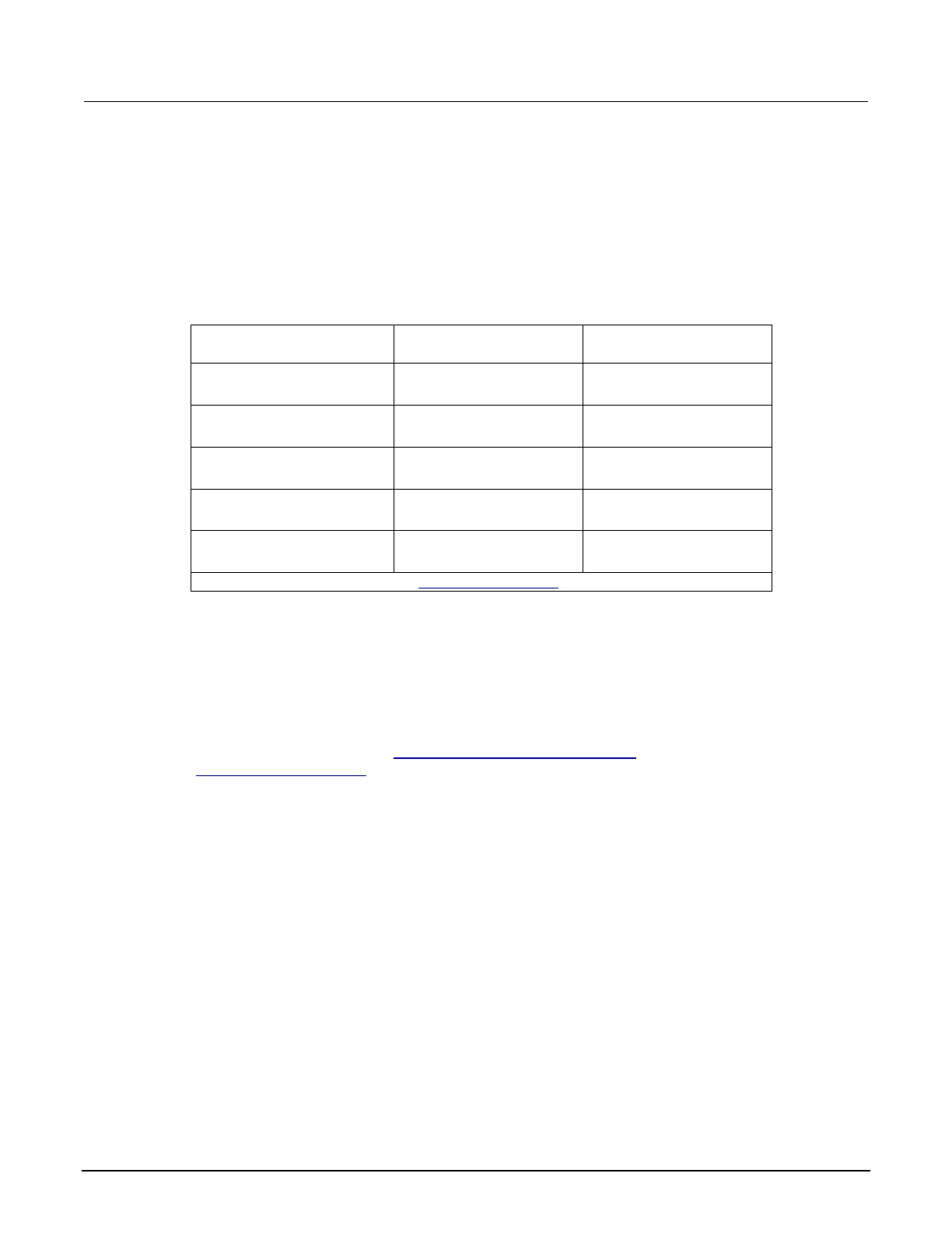
6. Verify output voltage accuracy for each of the voltages listed in the following table. For each test
point:
• Select the correct source range.
• Set the Model 2651A output voltage to the indicated value.
• Verify that the multimeter reading is within the limits given in the table.
Repeat the procedure for negative output voltages with the same magnitudes as those listed in
the following table, as applicable.
Output voltage accuracy limits
Source range Output voltage setting* Output voltage limits
(1 year, 18° C to 28° C)
100 mV 50.000 mV 49.490 mV to 50.510 mV
90.000 mV 89.482 mV to 90.518 mV
1 V 0.50000 V 0.49940 V to 0.50060 V
0.90000 V 0.89932 V to 0.90068 V
10 V 5.0000 V 4.9940 V to 5.0060 V
9.0000 V 8.9932 V to 9.0068 V
20 V 10.000 V 9.993 V to 10.007 V
18.000 V 17.991 V to 18.009 V
40 V 20.000 V 19.984 V to 20.016 V
36.000 V 35.981 V to 36.019 V
* Modify voltage limits if necessary. See Source limits calculations (on page B-3).
Voltage measurement accuracy
Follow the steps below to verify that the Model 2651A voltage measurement accuracy is within
specified limits. The test involves setting the source voltage, as measured by a precision digital
multimeter, and then verifying that the Model 2651A voltage readings are within required limits.
1. With the power off, connect the digital multimeter to the Model 2651A output terminals using 4-
wire connections, (the same Connections for voltage verification
(on page B-13) as shown in
Voltage source accuracy
(on page B-13)).
2. Select the multimeter DC volts function.
3. Enable the Model 2651A 4-wire (remote sense) mode by pressing CONFIG then MEAS, then
select V-MEAS > SENSE-MODE > 4-WIRE.
4. Set the Model 2651A to both source and measure voltage by pressing the SRC and then the
MEAS keys.

 Loading...


