FlexLine plus, Programs
103
7.13.2 Basic Terms
Elements of a road
project
Road projects consist, in general, of a horizontal and a vertical alignment.
Horizontal
geometry elements
For onboard input Road 3D supports the following elements for horizontal alignments.
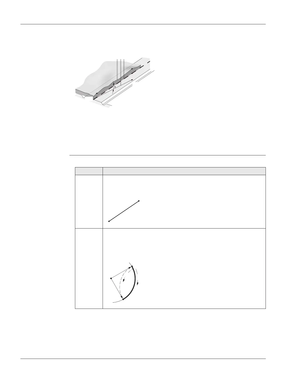
Any project point P1 has E, N and H coordinates
in a determined coordinate system and has three
positions.
P1' Position on natural surface
P1" Position on vertical alignment
P1'" Position on horizontal alignment
With a second point P2 the alignment is defined.
P1' P2'
Projection of the alignment onto the
natural surface.
P1'' P2''
Vertical alignment
P1''' P2'''
Horizontal alignment
Grade angle between the vertical and
horizontal alignment.
a Natural surface
b Horizontal alignment
c Vertical alignment
TSOX_108
P1’
P1’’’
P2’
P2’’
abc
P2’’’
P1’’
Element Description
Straight A straight has to be defined by:
• Start point (P1) and end point (P2) with known Easting and Northing
coordinates.
P1 Start point
P2 End point
Curve A circular curve has to be defined by:
• Start point (P1) and end point (P2) with known Easting and Northing
coordinates.
• Radius (R).
• Direction: Clockwise (b) or Anticlockwise (a).
P1 Start point
P2 End point
RRadius
a Anticlockwise direction
bClockwise direction
TSOX_ 109
P1
P2
TSOX_090
P1
R
R
b
a
P2