FlexLine plus, Check & Adjust
158
14.4 Adjusting the Compensator
Compensator index
error
The compensator index errors (l, t) occur, if the vertical axis of the instrument and the
plumb line are parallel but the zero points of the compensator and the circular level
do not coincide. The calibration procedure electronically adjusts the zero point of the
compensator.
A longitudinal component in direction of the telescope and a transversal component
perpendicular to the telescope define the plane of the dual axis compensator of the
instrument.
The longitudinal compensator index error (l) has a similar effect as the vertical index
error and effects all vertical angle readings.
The transversal compensator index error (t) is similar to the tilting axis error. The
effect of this error to the horizontal angle readings is 0 at the horizon and increases
with steep sightings.
Access 1) Select Tools from the Main Menu.
2) Select Adjust from the Tools Menu.
3) Select Comp. Index.
Check and adjust
step-by-step
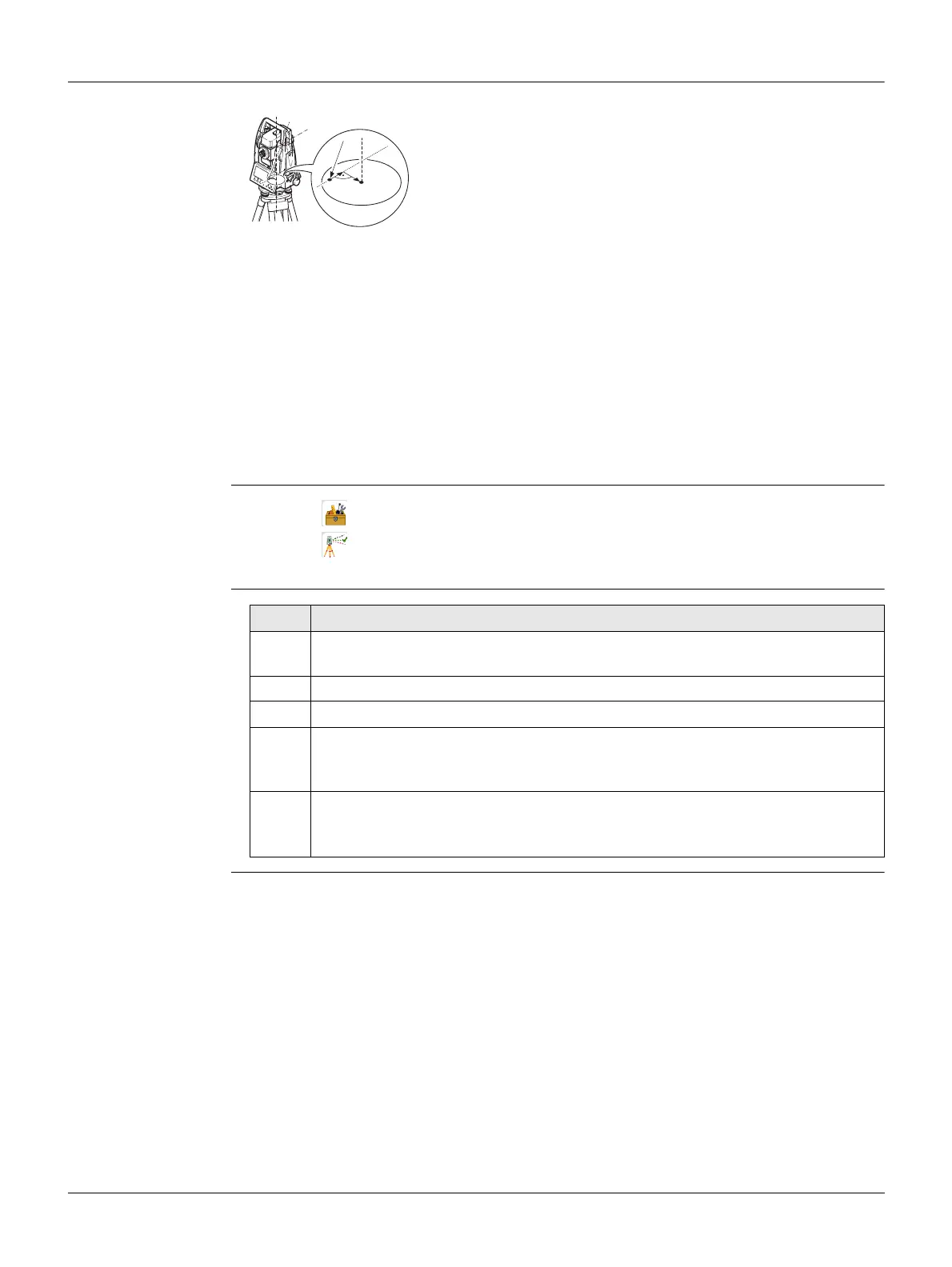
a) Mechanical vertical axis of the instrument, also called
standing axis
b) Plumb line
c) Longitudinal component (l) of the compensator index error
d) Transversal component (t) of the compensator index error
b
a
TSOX_141
c
ba
d
Step Description
1. Level the instrument with the electronic level. Refer to "4 Operation" - "Level
up with the electronic level step-by-step".
2. Press Store to measure the first face. No target has to be aimed at.
3. Store to release the measurement in the other face.
If one or more errors are bigger than the predefined limits, the procedure
must be repeated. All measurements of the current run are rejected and are
not averaged with the results from previous runs.
4. Measure the target.
The standard deviations of the determined adjustment errors can be calcu-
lated from the second run onwards.