FlexLine plus, Programs
70
7.5.3 Defining the Reference Line
Description The base line can be offset from, either longitudinally, in parallel or vertically, or be
rotated around the first base point. This new line created from the offsets is called
the reference line. All measured data refers to the reference line.
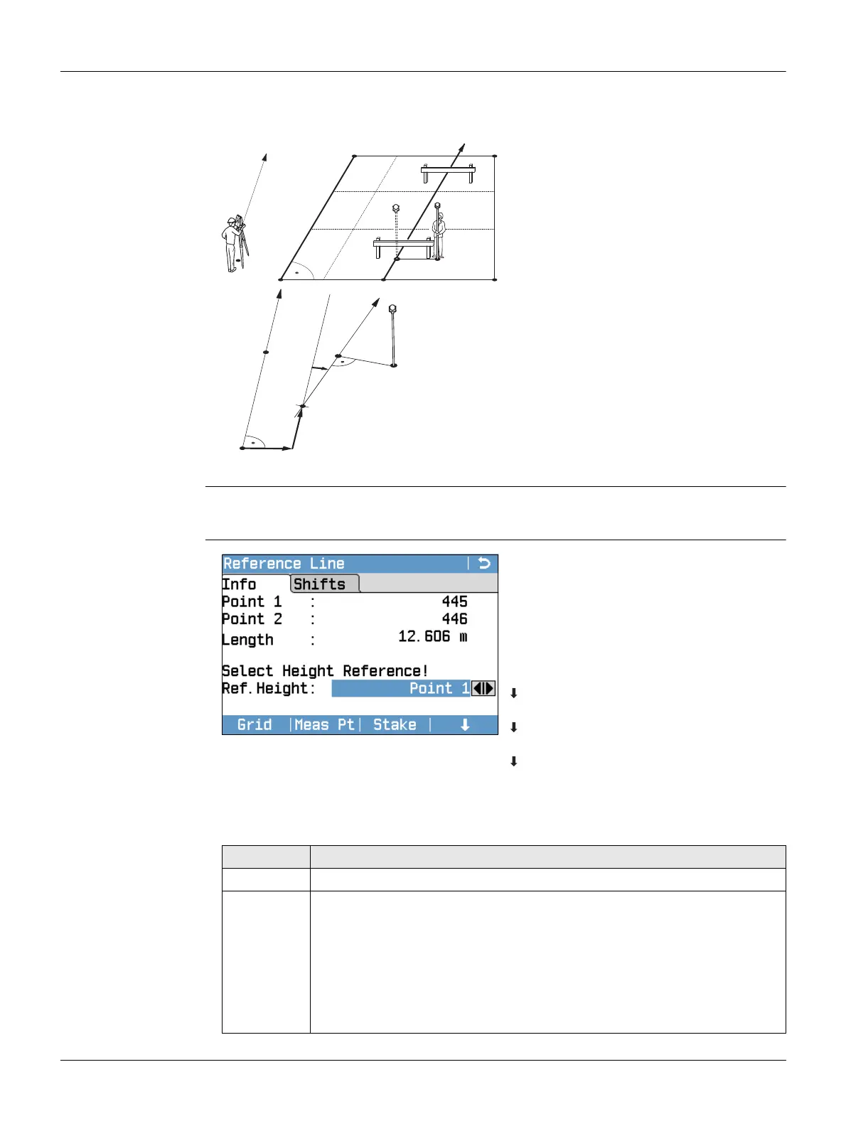
Access After completing the measurements required for defining the base line, the Reference
Line - Info screen will appear.
Reference Line - Info
P0 Instrument station
P1 Start point
P2 End point
d1 Base line
d2 Reference line
P1 Base point
P2 Base point
aBase line
d1 Parallel offset
d2 Longitudinal offset
P3 Reference point
r+ Rotation parameter
b Reference line
d1
d2
P1
P2
P0
TSOX_034
a
b
d2
d1
P1
P2
P3
TSOX_034a
r+
Grid
To stake out a grid relative to the
reference line.
Meas Pt
To measure Line & Offset.
Stake
To stake out points orthogonal to the
reference line.
NewBL
To define a new base line.
Shift=0
To reset all offset values to 0.
Segment
To subdivide a reference line into a
definable number of segments and
stake out the new points on the refer-
ence line.
Field Description
Length Length of the base line.
Ref. Height Point 1 Height differences are computed relative to the height
of the first reference point.
Point 2 Height differences are computed relative to the height
of the second reference point.
Interpolated Height differences are computed along the reference
line.
No Height Height differences are not computed or shown.