Troubleshooting and Maintenance
7
Troubleshooting and Maintenance
This chapter explains how to troubleshoot a problem when inverter protective functions, fault
trips, warning signals, or faults occur. If the inverter does not work normally after following the
suggested troubleshooting steps, please contact the LSIS Customer Support.
7.1
Protection Functions
7.1.1
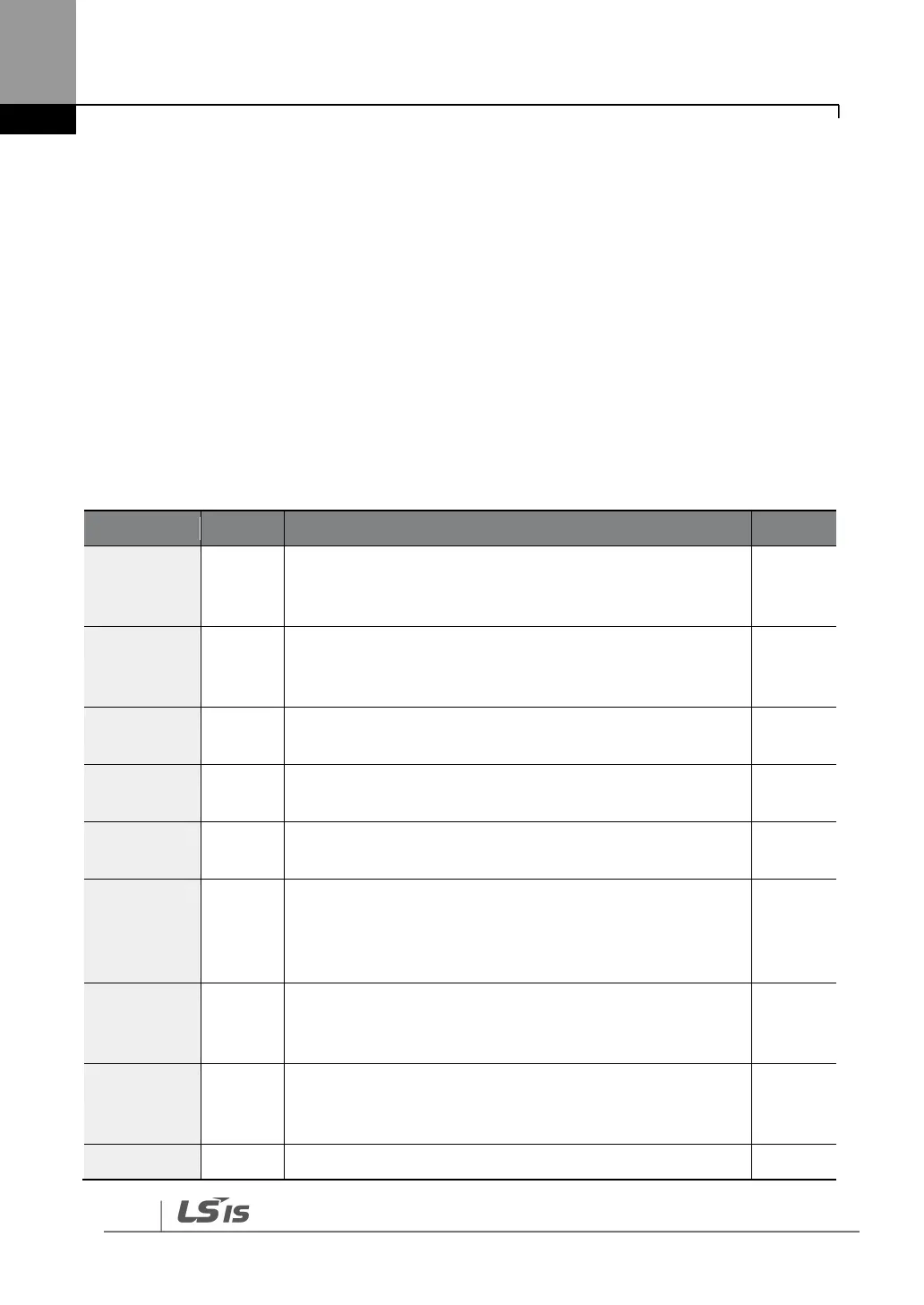
Protection from Output Current and Input Voltage
Displayed when the motor overload trip is activated and the
actual load level exceeds the set level. Operates when PRT-
20 is set to any value other than “0”.
Displayed when the motor underload trip is activated and
the actual load level is less than the set level. Operates when
PRT-27 is set to any value other than “0”.
Displayed when the inverter output current exceeds 200%
of the rated current.
Displayed when the internal DC circuit voltage exceeds the
specified value.
Displayed when the internal DC circuit voltage is less than
the specified value.
Displayed when a ground fault trip occurs on the output
side of the inverter and causes the current to exceed the
specified value. The specified value varies depending on the
inverter capacity.
Displayed based on inverse time limit thermal
characteristics to prevent motor overheating. Operates
when PRT-40 is set to any value other than “0”.
Displayed when a 3-phase inverter output has one or more
phases in an open circuit condition. Operates when bit 1 of
PRT-05 is set to “1”.
Displayed when a 3-phase inverter input has one or more